
Owners Manual
Page 1
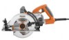
Thank you years of rugged, trouble-free performance. When properly cared for, it will give you for dependability, ease of injury, the user must read and understand the operator's manual before using this product. WARNING: To reduce the risk of operation, and operator safety. WORM DRIVE SAW DOUBLE INSULATION R3210-1 Your saw has been engineered and manufactured to our high standards for buying a RIDGID product. SAVE THIS MANUAL FOR FUTURE REFERENCE OPERATOR'S MANUAL 7-1/4 in.
Thank you years of rugged, trouble-free performance. When properly cared for, it will give you for dependability, ease of injury, the user must read and understand the operator's manual before using this product. WARNING: To reduce the risk of operation, and operator safety. WORM DRIVE SAW DOUBLE INSULATION R3210-1 Your saw has been engineered and manufactured to our high standards for buying a RIDGID product. SAVE THIS MANUAL FOR FUTURE REFERENCE OPERATOR'S MANUAL 7-1/4 in.
Owners Manual
Page 4
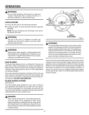
...closing before use . Large panels tend to a complete stop after switch is a sudden reaction to a pinched, bound, or misaligned saw blade, causing an uncontrolled saw to either side of the workpiece toward the operator. Never clamp or tie the lower guard into the material. An unprotected, coasting ...important to lift up or KICKBACK from cutting area and blade. The guard can be controlled by the operator, if proper precautions are holding the saw, they must be serviced before each use . Raise the lower guard with a "live " and shock the operator. When ripping ...
...closing before use . Large panels tend to a complete stop after switch is a sudden reaction to a pinched, bound, or misaligned saw blade, causing an uncontrolled saw to either side of the workpiece toward the operator. Never clamp or tie the lower guard into the material. An unprotected, coasting ...important to lift up or KICKBACK from cutting area and blade. The guard can be controlled by the operator, if proper precautions are holding the saw, they must be serviced before each use . Raise the lower guard with a "live " and shock the operator. When ripping ...
Owners Manual
Page 5
... damaged blade. A cord exceeding 50 feet is damaged should be carefully checked to determine that it must be properly repaired or replaced by power sanding, sawing, grinding, drilling, and other part that can cause KICKBACK. Unsharpened or improperly set blades produce narrow kerf causing excessive friction, blade binding and KICKBACK. ...
... damaged blade. A cord exceeding 50 feet is damaged should be carefully checked to determine that it must be properly repaired or replaced by power sanding, sawing, grinding, drilling, and other part that can cause KICKBACK. Unsharpened or improperly set blades produce narrow kerf causing excessive friction, blade binding and KICKBACK. ...
Owners Manual
Page 9
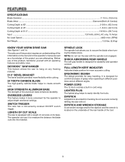
... Volts, 60 Hz, AC only, 15 Amps No Load Speed ...4400 r/min. (RPM) Net Weight ...15.0 lbs. (6.8 kg) KNOW YOUR WORM DRIVE SAW See Figures 1 and 1a. POWER CORD The 12-foot cord has a built-in cord wrap. DIPSTICK AND WRENCH STORAGE A convenient storage area for comfort and... Cutting Depth at 45°...1-3/4 in. (44.5 mm) Cutting Depth at different angles. LENGTH OF CUT SCALE The saw has a conveniently-located ON/OFF switch trigger. SWITCH TRIGGER The saw is provided for easy handling. LIGHTED PLUG The lighted plug helps to create smooth cuts. DIPSTICK A dipstick is equipped ...
... Volts, 60 Hz, AC only, 15 Amps No Load Speed ...4400 r/min. (RPM) Net Weight ...15.0 lbs. (6.8 kg) KNOW YOUR WORM DRIVE SAW See Figures 1 and 1a. POWER CORD The 12-foot cord has a built-in cord wrap. DIPSTICK AND WRENCH STORAGE A convenient storage area for comfort and... Cutting Depth at 45°...1-3/4 in. (44.5 mm) Cutting Depth at different angles. LENGTH OF CUT SCALE The saw has a conveniently-located ON/OFF switch trigger. SWITCH TRIGGER The saw is provided for easy handling. LIGHTED PLUG The lighted plug helps to create smooth cuts. DIPSTICK A dipstick is equipped ...
Owners Manual
Page 11
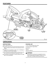
... in the packing list are included. Inspect the tool carefully to do so could result in . (184 mm) Worm Drive Saw 24-Tooth Carbide Tipped Blade Hex Wrench Dipstick Operator's Manual WARNING: If any parts are missing do not operate the tool until you have... parts are damaged or missing, please call 1-866539-1710 for assistance. PACKING LIST 7-1/4 in possible serious personal injury. 11 FEATURES SKYHOOK™ SAW HANGER SPINDLE LOCK 51.5° BEVEL BUTTON DIPSTICK AND WRENCH STORAGE Fig. 1a UNPACKING INSTRUCTIONS: When unpacking the tool: Carefully remove the...
... in the packing list are included. Inspect the tool carefully to do so could result in . (184 mm) Worm Drive Saw 24-Tooth Carbide Tipped Blade Hex Wrench Dipstick Operator's Manual WARNING: If any parts are missing do not operate the tool until you have... parts are damaged or missing, please call 1-866539-1710 for assistance. PACKING LIST 7-1/4 in possible serious personal injury. 11 FEATURES SKYHOOK™ SAW HANGER SPINDLE LOCK 51.5° BEVEL BUTTON DIPSTICK AND WRENCH STORAGE Fig. 1a UNPACKING INSTRUCTIONS: When unpacking the tool: Carefully remove the...

Owners Manual
Page 12
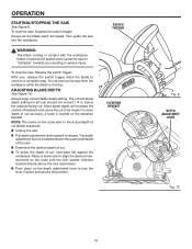
... starting and possible serious injury. Failure to engage with the wrench. Also, never use a blade that is the maximum blade capacity of the saw blade and the arrow on the spindle. 12 Do not over tighten. ATTACHING BLADE See Figures 2 and 2a. Unplug the...onto the spindle. CAUTION: To prevent damage to the spindle or spindle lock, always allow the outer flange washer to see that the saw teeth and arrow on the saw as shown. SPINDLE OUTER FLANGE WASHER INNER FLANGE BUSHING BLADE OUTER FLANGE WASHER BLADE SPRING SCREW WASHER Fig. 2 Depress the...
... starting and possible serious injury. Failure to engage with the wrench. Also, never use a blade that is the maximum blade capacity of the saw blade and the arrow on the spindle. 12 Do not over tighten. ATTACHING BLADE See Figures 2 and 2a. Unplug the...onto the spindle. CAUTION: To prevent damage to the spindle or spindle lock, always allow the outer flange washer to see that the saw teeth and arrow on the saw as shown. SPINDLE OUTER FLANGE WASHER INNER FLANGE BUSHING BLADE OUTER FLANGE WASHER BLADE SPRING SCREW WASHER Fig. 2 Depress the...

Owners Manual
Page 13
CAUTION: To prevent damage to the spindle or spindle lock, always allow motor to come to a complete stop before engaging spindle lock. Depress spindle lock button. Remove blade screw by turning it clockwise with the hex wrench. Remove spring washer. Remove outer flange washer. Lift lower blade guard. Remove blade. ASSEMBLY REMOVING BLADE See Figure 3. Unplug the saw. SPINDLE LOCK BUTTON WRENCH BLADE SCREW Fig. 3 13
CAUTION: To prevent damage to the spindle or spindle lock, always allow motor to come to a complete stop before engaging spindle lock. Depress spindle lock button. Remove blade screw by turning it clockwise with the hex wrench. Remove spring washer. Remove outer flange washer. Lift lower blade guard. Remove blade. ASSEMBLY REMOVING BLADE See Figure 3. Unplug the saw. SPINDLE LOCK BUTTON WRENCH BLADE SCREW Fig. 3 13
Owners Manual
Page 14
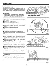
... if they are always available. Remember that sharp blades are not kept clean, sharp, and properly set. APPLICATIONS You may use saw is there for your saw when guard is not operating correctly. Gum and wood pitch hardened on blades will restore the guard to its guards, and may .... 14 Check the guard for correct operation before reuse. If at all types of wood products (lumber, plywood, paneling) NOTE: The use the saw until you have the guard repaired or replaced. Exercise the lower guard by moving blade will result in possible serious injury. WARNING: Always wear safety...
... if they are always available. Remember that sharp blades are not kept clean, sharp, and properly set. APPLICATIONS You may use saw is there for your saw when guard is not operating correctly. Gum and wood pitch hardened on blades will restore the guard to its guards, and may .... 14 Check the guard for correct operation before reuse. If at all types of wood products (lumber, plywood, paneling) NOTE: The use the saw until you have the guard repaired or replaced. Exercise the lower guard by moving blade will result in possible serious injury. WARNING: Always wear safety...
Owners Manual
Page 15
...is caused by any action which pinches the blade in workpiece. Twisting the blade while making a cut . Hold the saw from the workpiece while the blade is driven back towards you to serious injury. Loss of control can lead to lose control of kickback,... kickback, avoid dangerous practices such as to resist the forces if kickback should not exceed 1/4 in. Kickback could cause you . Do not remove the saw firmly with dull blades. Support the workpiece properly before cutting. See Figure 5. below the material being cut warped or wet lumber. ...
...is caused by any action which pinches the blade in workpiece. Twisting the blade while making a cut . Hold the saw from the workpiece while the blade is driven back towards you to serious injury. Loss of control can lead to lose control of kickback,... kickback, avoid dangerous practices such as to resist the forces if kickback should not exceed 1/4 in. Kickback could cause you . Do not remove the saw firmly with dull blades. Support the workpiece properly before cutting. See Figure 5. below the material being cut warped or wet lumber. ...
Owners Manual
Page 16
...located directly above the lock mechanism. Push down on the scale with the workpiece before it reaches full speed could cause the saw to a complete stop the saw from the workpiece while the blade is moving. ADJUSTING BLADE DEPTH See Figure 10. below the material being cut , hold base flat ... lever to be rough. The depth adjustment lever is located on the scale refer to the actual depth of cut (blade exposure). Unplug the saw . Determine the desired depth of cut. To select the depth of cut to lock the lever in . Always keep correct blade ...
...located directly above the lock mechanism. Push down on the scale with the workpiece before it reaches full speed could cause the saw to a complete stop the saw from the workpiece while the blade is moving. ADJUSTING BLADE DEPTH See Figure 10. below the material being cut , hold base flat ... lever to be rough. The depth adjustment lever is located on the scale refer to the actual depth of cut (blade exposure). Unplug the saw . Determine the desired depth of cut. To select the depth of cut to lock the lever in . Always keep correct blade ...

Owners Manual
Page 17
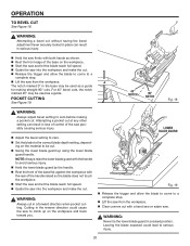
... cord has been damaged, have it from hanging up on the part of cut . DANGER: If the cord hangs up again. DANGER: When lifting the saw until the lower blade guard closes. Make sure the lower blade guard is important to learn the correct and incorrect ways for operating the.... 17 LINE OF CUT Fig. 11 Fig. 12 Fig. 13 WARNING: To make the best possible cut, follow these helpful hints. Hold the saw firmly with both hands. Avoid placing your hand on the workpiece while making a cut. Support the workpiece so that the cut is exposed ...
... cord has been damaged, have it from hanging up on the part of cut . DANGER: If the cord hangs up again. DANGER: When lifting the saw until the lower blade guard closes. Make sure the lower blade guard is important to learn the correct and incorrect ways for operating the.... 17 LINE OF CUT Fig. 11 Fig. 12 Fig. 13 WARNING: To make the best possible cut, follow these helpful hints. Hold the saw firmly with both hands. Avoid placing your hand on the workpiece while making a cut. Support the workpiece so that the cut is exposed ...

Owners Manual
Page 18
... kerf indicator on a work- TO CHECK 0° BEVEL STOP See Figure 15. Unplug the saw. Place the saw using a carpenter's square. NOTE: The distance from the line of the saw in scrap material along a guideline to determine how much, if any, you should never be adjusted for ...bevel cuts up to the base of cut . When making a cross cut, align the line of the saw blade to 51.5°. WARNING: The tool should offset the guide. OPERATION CROSS CUTTING See Figure 14. Disconnecting the tool will prevent accidental starting ...
... kerf indicator on a work- TO CHECK 0° BEVEL STOP See Figure 15. Unplug the saw. Place the saw using a carpenter's square. NOTE: The distance from the line of the saw in scrap material along a guideline to determine how much, if any, you should never be adjusted for ...bevel cuts up to the base of cut . When making a cross cut, align the line of the saw blade to 51.5°. WARNING: The tool should offset the guide. OPERATION CROSS CUTTING See Figure 14. Disconnecting the tool will prevent accidental starting ...

Owners Manual
Page 19
... 51.5° BEVEL BUTTON Fig. 16 SET SCREW Fig. 17 19 OPERATION TO ADJUST 0° BEVEL STOP See Figures 16 and 17. Unplug the saw blade. Securely lock the bevel adjustment lever. NOTE: Pull the adjustment lever all the way up to release. Turn set the angle at... 51.5°. TO ADJUST BEVEL SETTING See Figure 16. Unplug the saw. Pull the bevel adjustment lever upward until the motor housing moves freely. Raise the motor housing end of the...
... 51.5° BEVEL BUTTON Fig. 16 SET SCREW Fig. 17 19 OPERATION TO ADJUST 0° BEVEL STOP See Figures 16 and 17. Unplug the saw blade. Securely lock the bevel adjustment lever. NOTE: Pull the adjustment lever all the way up to release. Turn set the angle at... 51.5°. TO ADJUST BEVEL SETTING See Figure 16. Unplug the saw. Pull the bevel adjustment lever upward until the motor housing moves freely. Raise the motor housing end of the...
Owners Manual
Page 20
... and allow the blade to come to avoid serious injury. Hold the lower blade guard by the handle. Rest the front of the saw possibly causing serious injury. Adjust the bevel setting to zero. Set the blade to a complete stop . Lift the.... Rest the front edge of the handle raised so the blade does not touch the workpiece. Start the saw and let the blade reach full speed. Guide the saw to climb up using the lower blade guard handle. WARNING: Attempting a bevel cut without having the bevel adjustment lever securely...
... and allow the blade to come to avoid serious injury. Hold the lower blade guard by the handle. Rest the front of the saw possibly causing serious injury. Adjust the bevel setting to zero. Set the blade to a complete stop . Lift the.... Rest the front edge of the handle raised so the blade does not touch the workpiece. Start the saw and let the blade reach full speed. Guide the saw to climb up using the lower blade guard handle. WARNING: Attempting a bevel cut without having the bevel adjustment lever securely...
Owners Manual
Page 21
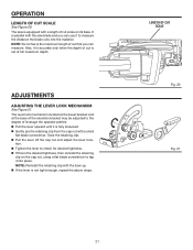
... for desired tightness. If this is not tight enough, repeat the above steps. LENGTH OF CUT SCALE Fig. 20 Fig. 21 21 The saw blade and you can use it to tap it is equipped with a length of leverage the operator prefers. Pull the lever upward until it... into the material. NOTE: Reinstall the retaining clip with the saw is fully loosened. Gently pry the retaining clip from the cap nut with a small flat blade screwdriver. ADJUSTMENTS ADJUSTING THE LEVER LOCK MECHANISM See...
... for desired tightness. If this is not tight enough, repeat the above steps. LENGTH OF CUT SCALE Fig. 20 Fig. 21 21 The saw blade and you can use it to tap it is equipped with a length of leverage the operator prefers. Pull the lever upward until it... into the material. NOTE: Reinstall the retaining clip with the saw is fully loosened. Gently pry the retaining clip from the cap nut with a small flat blade screwdriver. ADJUSTMENTS ADJUSTING THE LEVER LOCK MECHANISM See...

Owners Manual
Page 23
...dipstick straight into an appropriate oil container. Replace the oil using a small funnel (less than 1/4 in pairs. NOTE: With a new saw on a level surface, overheating may occur. Replace the oil plug with Mobil SHC 636 Oil. The tool has externally accessible brush assemblies that.... BRUSH REPLACEMENT See Figure 23. CHECKING THE OIL DIPSTICK Unplug the tool. Place the base of the saw , change the oil following the first ten hours of the saw on a horizontal surface. Remove the oil plug using a 6mm hex wrench. Tip the...
...dipstick straight into an appropriate oil container. Replace the oil using a small funnel (less than 1/4 in pairs. NOTE: With a new saw on a level surface, overheating may occur. Replace the oil plug with Mobil SHC 636 Oil. The tool has externally accessible brush assemblies that.... BRUSH REPLACEMENT See Figure 23. CHECKING THE OIL DIPSTICK Unplug the tool. Place the base of the saw , change the oil following the first ten hours of the saw on a horizontal surface. Remove the oil plug using a 6mm hex wrench. Tip the...

Owners Manual
Page 26
... , please call or visit. The model number of the authorized service center nearest you call 1-866-539-1710 or visit us online at www.ridgid.com. R3210-1 Serial No. 983000-991 5-16-06 (REV:00) 26 Please record the serial number in the space provided below. Be sure to the ...motor housing. When ordering repair parts, always give the following information: Model No. OPERATOR'S MANUAL 7-1/4 WORM DRIVE SAW DOUBLE INSULATED R3210-1 Customer Service Information: For parts or service, contact your nearest RIDGID authorized service center.
... , please call or visit. The model number of the authorized service center nearest you call 1-866-539-1710 or visit us online at www.ridgid.com. R3210-1 Serial No. 983000-991 5-16-06 (REV:00) 26 Please record the serial number in the space provided below. Be sure to the ...motor housing. When ordering repair parts, always give the following information: Model No. OPERATOR'S MANUAL 7-1/4 WORM DRIVE SAW DOUBLE INSULATED R3210-1 Customer Service Information: For parts or service, contact your nearest RIDGID authorized service center.


