
Operating Instructions
Page 1
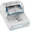
Image Scanner Operating Instructions Guide to read the Safety Information in this manual before you use this manual carefully before using the machine. For safe and correct use, be sure to Components Setting up the Scanner Installing Software Setting Originals Using the TWAIN Driver Appendix Read this machine and keep it handy for future reference.
Image Scanner Operating Instructions Guide to read the Safety Information in this manual before you use this manual carefully before using the machine. For safe and correct use, be sure to Components Setting up the Scanner Installing Software Setting Originals Using the TWAIN Driver Appendix Read this machine and keep it handy for future reference.
Operating Instructions
Page 2
...® and ISIS® are employed in this manual are subject to a power source as a guide only and is meant as above. Power Source Color Scanner: 120V, 60Hz, 10A or more Please be slightly different from the use of copying or printing certain items, consult with your local dealer. Important Contents...
...® and ISIS® are employed in this manual are subject to a power source as a guide only and is meant as above. Power Source Color Scanner: 120V, 60Hz, 10A or more Please be slightly different from the use of copying or printing certain items, consult with your local dealer. Important Contents...

Operating Instructions
Page 3
... at the End of the Daisy Chain) ...24 Connecting the SCSI Cable (When the Scanner is not at the End of the Daisy Chain) ...26 Using the Scanner only with the SCSI Connection 27 Connecting with USB Interface 28 Connecting with IEEE1394 Interface 29 Connecting to a ...33 Turning the Power Off 33 Using the Hard Reset Switch 34 3. Setting up the Scanner Confirmations Before the Setup 11 Location, Space and Environment 11 Disengaging the lock for This Scanner 5 How to This Scanner 7 Understanding Indicators 9 DIP Switches...10 2. Installing Software Installing TWAIN Driver 35 System ...
... at the End of the Daisy Chain) ...24 Connecting the SCSI Cable (When the Scanner is not at the End of the Daisy Chain) ...26 Using the Scanner only with the SCSI Connection 27 Connecting with USB Interface 28 Connecting with IEEE1394 Interface 29 Connecting to a ...33 Turning the Power Off 33 Using the Hard Reset Switch 34 3. Setting up the Scanner Confirmations Before the Setup 11 Location, Space and Environment 11 Disengaging the lock for This Scanner 5 How to This Scanner 7 Understanding Indicators 9 DIP Switches...10 2. Installing Software Installing TWAIN Driver 35 System ...

Operating Instructions
Page 4
Using the TWAIN Driver Procedure Breakdown 57 Scanning Originals 58 What You Can Do with the TWAIN Driver 60 Functions of the Scanner 81 How Data Size Changes Depending on the Exposure Glass 48 Placing the Originals in the ADF 64 When the Originals are Not... Under the Background Panel 74 Cleaning Inside the ADF Cover 76 Cleaning the Ventilation Panel 77 Moving and Transporting the Scanner 78 Moving Over Short Distances 78 Transporting the Scanner 79 Disposing of the TWAIN Driver 60 6. Setting Originals Sizes and Weights of Recommended Originals 45 Original Sizes Available ...
Using the TWAIN Driver Procedure Breakdown 57 Scanning Originals 58 What You Can Do with the TWAIN Driver 60 Functions of the Scanner 81 How Data Size Changes Depending on the Exposure Glass 48 Placing the Originals in the ADF 64 When the Originals are Not... Under the Background Panel 74 Cleaning Inside the ADF Cover 76 Cleaning the Ventilation Panel 77 Moving and Transporting the Scanner 78 Moving Over Short Distances 78 Transporting the Scanner 79 Disposing of the TWAIN Driver 60 6. Setting Originals Sizes and Weights of Recommended Originals 45 Original Sizes Available ...
Operating Instructions
Page 6
.... • Disposal can create the risk of electric shock. • Never remove any covers or screws other than those specified in this scanner in any way. This can take place at our authorized dealer or at appropriate collection sites. • Keep the machine away from the ... use with a power source with a voltage different from flammable liquids, gases, and aerosols. Have all inspections, adjustments, and repairs inside of the scanner contains high-voltage components that in . A fire or an electric shock might occur. • Make sure the wall outlet is near the machine and...
.... • Disposal can create the risk of electric shock. • Never remove any covers or screws other than those specified in this scanner in any way. This can take place at our authorized dealer or at appropriate collection sites. • Keep the machine away from the ... use with a power source with a voltage different from flammable liquids, gases, and aerosols. Have all inspections, adjustments, and repairs inside of the scanner contains high-voltage components that in . A fire or an electric shock might occur. • Make sure the wall outlet is near the machine and...

Operating Instructions
Page 7
... damage to the cord, fire or electrical shock. • Be careful not to pinch your fingers when closing the Automatic Document Feeder (ADF). • This scanner weighs approximately 72.8 lbs. • Make sure to hold onto the plug. Do not pull on the cord. This can cause injury. • When transporting...
... damage to the cord, fire or electrical shock. • Be careful not to pinch your fingers when closing the Automatic Document Feeder (ADF). • This scanner weighs approximately 72.8 lbs. • Make sure to hold onto the plug. Do not pull on the cord. This can cause injury. • When transporting...

Operating Instructions
Page 9
Note ❒ There is provided as a PDF file. This manual is a CD-ROM that comes with this scanner. 5 To enhance safe and efficient operation of this scanner, all of this manual) Provides all users should read and follow the instructions carefully. ❖ Quick Installation Guide Describes how to install, set up, and use the scanner. Manuals for This Scanner The following manuals describe the operational and maintenance procedures of the information how to install the scanner. ❖ Operating Instructions (this machine.
Note ❒ There is provided as a PDF file. This manual is a CD-ROM that comes with this scanner. 5 To enhance safe and efficient operation of this scanner, all of this manual) Provides all users should read and follow the instructions carefully. ❖ Quick Installation Guide Describes how to install, set up, and use the scanner. Manuals for This Scanner The following manuals describe the operational and maintenance procedures of the information how to install the scanner. ❖ Operating Instructions (this machine.

Operating Instructions
Page 11
... validate the When you to automatically load multi- with the ADF, set the operation mode of this scanner. ⇒ p.10 "DIP Switches" ple originals into this machine. 2. After scanning, return the switch to the scanner. DIP Switches er) Allows you scan the thick originals - Original Stopper Stops the originals scanned by the... changeover lever to start the manual scanning 12. ADF (Automatic Document Feed- 7. Power Switch Turns this key to your side. Rotary Switch 9. Use to This Scanner ADC002S 1. Paper Thickness Changeover Le- 1.
... validate the When you to automatically load multi- with the ADF, set the operation mode of this scanner. ⇒ p.10 "DIP Switches" ple originals into this machine. 2. After scanning, return the switch to the scanner. DIP Switches er) Allows you scan the thick originals - Original Stopper Stops the originals scanned by the... changeover lever to start the manual scanning 12. ADF (Automatic Document Feed- 7. Power Switch Turns this key to your side. Rotary Switch 9. Use to This Scanner ADC002S 1. Paper Thickness Changeover Le- 1.

Operating Instructions
Page 13
All indicators on: For a short while after you turned on : See p.63 "Error Indicators" 9 All indicators blinking: System error. Guide to This Scanner Understanding Indicators This section explains how to the ADF No error or the current status Scan Wait SADF When SADF mode or during standby for ...
All indicators on: For a short while after you turned on : See p.63 "Error Indicators" 9 All indicators blinking: System error. Guide to This Scanner Understanding Indicators This section explains how to the ADF No error or the current status Scan Wait SADF When SADF mode or during standby for ...

Operating Instructions
Page 14
...3 SCSI termination enable disable 4 5 6 (system usage) 7 always OFF Do not make changes. 8 *1 SCAM: SCSI Configured Automatically. In this scanner with the SCAM function enabled are connected to the daisy chain. You can turn the DIP Switch No.2 ON (SCSI synchronous transmission disabled). ❒ ...When the scanner is set. In that case, turn the DIP Switch No.2 OFF (SCSI synchronous transmission enabled) when using the scanner only with the SCSI connection. ❒ A malfunction with the Rotary Switch. ...
...3 SCSI termination enable disable 4 5 6 (system usage) 7 always OFF Do not make changes. 8 *1 SCAM: SCSI Configured Automatically. In this scanner with the SCAM function enabled are connected to the daisy chain. You can turn the DIP Switch No.2 ON (SCSI synchronous transmission disabled). ❒ ...When the scanner is set. In that case, turn the DIP Switch No.2 OFF (SCSI synchronous transmission enabled) when using the scanner only with the SCSI connection. ❒ A malfunction with the Rotary Switch. ...
Operating Instructions
Page 15
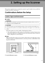
...Location R WARNING: • Make sure the wall outlet is enough space to get it could cause injury. Setting up the Scanner This section explains how to setup the scanner to provide the clearance as illustrated below, and also provide a comfortable working area in event of an emergency it can be ... difference of heights between one end and the other of the surface for use, and how to a level surface). ❖ Space Make sure that the scanner is in a location where there is near the machine and easily accessible so that in the front. 1. 4 inch (100 mm) or more ADC120S 2....
...Location R WARNING: • Make sure the wall outlet is enough space to get it could cause injury. Setting up the Scanner This section explains how to setup the scanner to provide the clearance as illustrated below, and also provide a comfortable working area in event of an emergency it can be ... difference of heights between one end and the other of the surface for use, and how to a level surface). ❖ Space Make sure that the scanner is in a location where there is near the machine and easily accessible so that in the front. 1. 4 inch (100 mm) or more ADC120S 2....

Operating Instructions
Page 16
...may be the cause of the malfunction. • In a location exposed to direct sunlight • In a location where the scanner will be used if it is necessary to transport the scanner in the future. ❒ When the machine is moved from a cold location to extreme temperatures or humidity • Near ... where the temperature and humidity will fall within the ranges shown below. ADC123S Important ❒ Save the box and cushioning material in which the scanner was packed so that they can be subjected to blowing air or radi- 2 ant heat, such as near an air conditioner or heater •...
...may be the cause of the malfunction. • In a location exposed to direct sunlight • In a location where the scanner will be used if it is necessary to transport the scanner in the future. ❒ When the machine is moved from a cold location to extreme temperatures or humidity • Near ... where the temperature and humidity will fall within the ranges shown below. ADC123S Important ❒ Save the box and cushioning material in which the scanner was packed so that they can be subjected to blowing air or radi- 2 ant heat, such as near an air conditioner or heater •...

Operating Instructions
Page 17
... back of this machine. 2 ADC082S Note ❒ Use a coin to remove the lock screws. ❒ Be sure to disengage the lock after you take the scanner out of the package for transportation In this machine. A Put the leg stopper of this section, we explain how to remove the lock screws. ADC084S...
... back of this machine. 2 ADC082S Note ❒ Use a coin to remove the lock screws. ❒ Be sure to disengage the lock after you take the scanner out of the package for transportation In this machine. A Put the leg stopper of this section, we explain how to remove the lock screws. ADC084S...

Operating Instructions
Page 18
... the "Unlock" position. 14 ADC025S ADC086S C Return the removed Background Panel to be kept fixing on the back of the Pressure Panel. Setting up the Scanner C The removed lock screws are to be kept on the back of the Pressure Panel as follows: A Lift the Pressure Panel and carefully pull out...
... the "Unlock" position. 14 ADC025S ADC086S C Return the removed Background Panel to be kept fixing on the back of the Pressure Panel. Setting up the Scanner C The removed lock screws are to be kept on the back of the Pressure Panel as follows: A Lift the Pressure Panel and carefully pull out...

Operating Instructions
Page 20
... it when pulling it out. 16 ADC010S Important ❒ The control unit is heavy. Note ❒ Use the accessory tool to re- Setting up the Scanner Installing Options Installing the Image-Processing Unit Important 2 ❒ Touch any metallic material before touching the image-processing unit to remove or fix the screws...
... it when pulling it out. 16 ADC010S Important ❒ The control unit is heavy. Note ❒ Use the accessory tool to re- Setting up the Scanner Installing Options Installing the Image-Processing Unit Important 2 ❒ Touch any metallic material before touching the image-processing unit to remove or fix the screws...

Operating Instructions
Page 21
... unit. ADC011S F Connect the connector at the bottom surface of the scanner control unit, and fix with seven screws, then insert the scanner control unit into the main unit. H Close the scanner control unit cover and fix with one accessory screw. Note ❒ Be sure to the connector of... the image-processing unit to place the scanner on the level surface when inserting the scanner control unit. ❒ Insert the scanner control unit till you see the screw holes. 17 Installing Options D Remove the seven screws on the...
... unit. ADC011S F Connect the connector at the bottom surface of the scanner control unit, and fix with seven screws, then insert the scanner control unit into the main unit. H Close the scanner control unit cover and fix with one accessory screw. Note ❒ Be sure to the connector of... the image-processing unit to place the scanner on the level surface when inserting the scanner control unit. ❒ Insert the scanner control unit till you see the screw holes. 17 Installing Options D Remove the seven screws on the...

Operating Instructions
Page 22
... unit with the USB in former state. terface board. B Remove the three screws on the center of the product. ADC009S C Pull out the scanner control unit by pulling the black ribbon on the lower back surface of the board. move static from your body. ADC010S Important ❒ The control ...
... unit with the USB in former state. terface board. B Remove the three screws on the center of the product. ADC009S C Pull out the scanner control unit by pulling the black ribbon on the lower back surface of the board. move static from your body. ADC010S Important ❒ The control ...

Operating Instructions
Page 23
ADC077S 19 ADC011S F Remove the USB 2.0 interface board fixed with 6 screws. Installing Options D Remove the seven screws on the cover of the scanner control unit. 2 ADC064S E Open the cover of the scanner control unit.
ADC077S 19 ADC011S F Remove the USB 2.0 interface board fixed with 6 screws. Installing Options D Remove the seven screws on the cover of the scanner control unit. 2 ADC064S E Open the cover of the scanner control unit.

Operating Instructions
Page 24
...ADC014S H Check that it is connected tightly, check that there are no foreign objects such as metal on the level surface when inserting the scanner control unit. ❒ Insert the scanner control unit till you see the screw holes. Fix the board with three screws. Setting up the... Scanner G Connect the IEEE1394 interface board to place the scanner on the scanner control unit. I Close the scanner control unit cover and fix with seven screws, then insert the scanner control unit into the main unit. Note ❒ Be sure to...
...ADC014S H Check that it is connected tightly, check that there are no foreign objects such as metal on the level surface when inserting the scanner control unit. ❒ Insert the scanner control unit till you see the screw holes. Fix the board with three screws. Setting up the... Scanner G Connect the IEEE1394 interface board to place the scanner on the scanner control unit. I Close the scanner control unit cover and fix with seven screws, then insert the scanner control unit into the main unit. Note ❒ Be sure to...

Operating Instructions
Page 25
... . When the "Found New Hardware Wizard" started before the software installation. Interfaces are switched automatically when you can connect the scanner to two computers at the same time from three computers. When the IEEE1394 interface board of the computer to the SCSI (Small... incorrect operation. One with the SCSI interface, and one with ANSI (American National Standard Institute). Though, you can connect the scanner to three computers at the same time from one of your service representative about the recommended SCSI board. 21 About the SCSI ...
... . When the "Found New Hardware Wizard" started before the software installation. Interfaces are switched automatically when you can connect the scanner to two computers at the same time from three computers. When the IEEE1394 interface board of the computer to the SCSI (Small... incorrect operation. One with the SCSI interface, and one with ANSI (American National Standard Institute). Though, you can connect the scanner to three computers at the same time from one of your service representative about the recommended SCSI board. 21 About the SCSI ...


