Operating Instructions
Page 1
Printed in this product and keep it handy for future reference. For safety, please follow the instructions in Japan EE GB G407-6657 Image Scanner OPERATING INSTRUCTIONS Image Scanner OPERATING INSTRUCTIONS Read this manual carefully before you use this manual.
Printed in this product and keep it handy for future reference. For safety, please follow the instructions in Japan EE GB G407-6657 Image Scanner OPERATING INSTRUCTIONS Image Scanner OPERATING INSTRUCTIONS Read this manual carefully before you use this manual.

Operating Instructions
Page 3
Declaration of Conformity "The Product complies with IEC417, this machine uses the following symbols for connections to host computer (and/or peripheral) in order to meet EMC Directive 89/336/EEC emission limits. In accordance with the requirements of the EMC Directive 89/336/EEC and the Low Voltage Directive 73/23/EEC." Caution Properly shielded and grounded cables and connectors must be used for the main switch: • a means Push ON Push OFF RICOH IMAGE SCANNER IS450S/IS450D/IS450SE/IS450DE Copyright © 1998
Declaration of Conformity "The Product complies with IEC417, this machine uses the following symbols for connections to host computer (and/or peripheral) in order to meet EMC Directive 89/336/EEC emission limits. In accordance with the requirements of the EMC Directive 89/336/EEC and the Low Voltage Directive 73/23/EEC." Caution Properly shielded and grounded cables and connectors must be used for the main switch: • a means Push ON Push OFF RICOH IMAGE SCANNER IS450S/IS450D/IS450SE/IS450DE Copyright © 1998

Operating Instructions
Page 4
...to correct the interference by the party responsible for the main switch: • a means Push ON Push OFF RICOH IMAGE SCANNER IS450S/IS450D/IS450SE/IS450DE Copyright © 1998 Remarque concernant les utilisateurs au Canada Cet appareil numérique de la Classe B ...Rules. If this equipment does cause harmful interference to radio communications. Declaration of Conformity Product Name: Scanner Model Number: RICOH IMAGE SCANNER IS450S/IS450D/IS450SE/IS450DE Responsible party: Ricoh Corporation Address: 5 Dedrick Place, West Caldwell, NJ 07006 Telephone number: 973-882-2000 This ...
...to correct the interference by the party responsible for the main switch: • a means Push ON Push OFF RICOH IMAGE SCANNER IS450S/IS450D/IS450SE/IS450DE Copyright © 1998 Remarque concernant les utilisateurs au Canada Cet appareil numérique de la Classe B ...Rules. If this equipment does cause harmful interference to radio communications. Declaration of Conformity Product Name: Scanner Model Number: RICOH IMAGE SCANNER IS450S/IS450D/IS450SE/IS450DE Responsible party: Ricoh Corporation Address: 5 Dedrick Place, West Caldwell, NJ 07006 Telephone number: 973-882-2000 This ...
Operating Instructions
Page 11
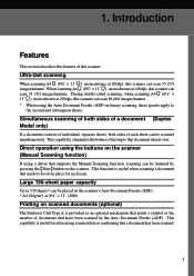
... Safety Information i Safety During Operation i Examples of a document Duplex Model only 1 Direct operation using the buttons on the scanner Manual Scanning function 1 Large 150-sheet paper capacity 1 Printing on scanned documents (optional 1 Space-saving design 2 Supports both TWAIN and... ISIS 2 Guide to the Scanner 3 Understanding the Indicators 5 2. Introduction Features 1...
... Safety Information i Safety During Operation i Examples of a document Duplex Model only 1 Direct operation using the buttons on the scanner Manual Scanning function 1 Large 150-sheet paper capacity 1 Printing on scanned documents (optional 1 Space-saving design 2 Supports both TWAIN and... ISIS 2 Guide to the Scanner 3 Understanding the Indicators 5 2. Introduction Features 1...

Operating Instructions
Page 13
... 34 Cleaning the White Roller (Duplex Model Only 36 Moving the Scanner 38 Carrying the Scanner a Short Distance 39 Shipping the Scanner 39 Disposing of Contents 6. Table of the Scanner 39 Options 40 Image Processing Unit Type A 40 Red Lamp Unit... Type A 40 Endorser Unit Type A(Printing Function 41 Specifications 42 Scanner Electrical and Hardware Specifications 42 DIP Switches 43 Functions 44 Preview 44 Scan 45 Scanning Composition...53 Gamma Correction 54 Binary Filters 55 Parameter Download 55 Document Size Detection 56 Erase Background 57 Index 58 ix
... 34 Cleaning the White Roller (Duplex Model Only 36 Moving the Scanner 38 Carrying the Scanner a Short Distance 39 Shipping the Scanner 39 Disposing of Contents 6. Table of the Scanner 39 Options 40 Image Processing Unit Type A 40 Red Lamp Unit... Type A 40 Endorser Unit Type A(Printing Function 41 Specifications 42 Scanner Electrical and Hardware Specifications 42 DIP Switches 43 Functions 44 Preview 44 Scan 45 Scanning Composition...53 Gamma Correction 54 Binary Filters 55 Parameter Download 55 Document Size Detection 56 Erase Background 57 Index 58 ix
Operating Instructions
Page 15
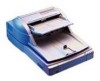
...needs to 150 sheets* can be initiated by the Auto Document Feeder (ADF). Simultaneous scanning of both sides of a document (Duplex Model only) If a document consists of individual, separate sheets, both sides of this scanner can be scanned simultaneously. During double-sided scanning, when... and subsequent sheets. Ultra-fast scanning When scanning A4K (8½" × 11"K), monochrome at 400dpi, this scanner. This capability eliminates the bother of documents that supports the Manual Scanning function, scanning can scan 31 (32) images/minute. When scanning A4K (8½"...
...needs to 150 sheets* can be initiated by the Auto Document Feeder (ADF). Simultaneous scanning of both sides of a document (Duplex Model only) If a document consists of individual, separate sheets, both sides of this scanner can be scanned simultaneously. During double-sided scanning, when... and subsequent sheets. Ultra-fast scanning When scanning A4K (8½" × 11"K), monochrome at 400dpi, this scanner. This capability eliminates the bother of documents that supports the Manual Scanning function, scanning can scan 31 (32) images/minute. When scanning A4K (8½"...

Operating Instructions
Page 16
Supports both TWAIN and ISIS The scanner supports both the standard TWAIN and the newer ISIS driver, allowing the scanner to be set up next to a wall, and permits office space to function with a wide range of software. 2 This design allows the scanner to be used more effectively. Introduction Space-saving design This scanner is designed in a "wingless" style, in which there are no protruding elements, such as a document tray. 1.
Supports both TWAIN and ISIS The scanner supports both the standard TWAIN and the newer ISIS driver, allowing the scanner to be set up next to a wall, and permits office space to function with a wide range of software. 2 This design allows the scanner to be used more effectively. Introduction Space-saving design This scanner is designed in a "wingless" style, in which there are no protruding elements, such as a document tray. 1.
Operating Instructions
Page 17
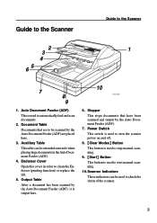
... is used to check the status of the scanner. 3 Output Table After a document has been scanned by the Auto Document Feeder (ADF) are placed here. 3. Guide to the Scanner Guide to automatically feed and scan documents. 2. Auxiliary Table This table can be extended outwards when placing large documents in order to start manual scanning. 10. Endorser...
... is used to check the status of the scanner. 3 Output Table After a document has been scanned by the Auto Document Feeder (ADF) are placed here. 3. Guide to the Scanner Guide to automatically feed and scan documents. 2. Auxiliary Table This table can be extended outwards when placing large documents in order to start manual scanning. 10. Endorser...
Operating Instructions
Page 18
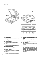
...is placed. 3. Power Connector Connect the power cable here. 5. This switch is used to set the SCSI ID. 6. Contact Glass This is where the document is an extension interface for reverse side scanning. (Duplex Model only) 8. Rotary Switch This switch is used to set the operating mode. 9. ADF Cover... Open this cover to make new DIP switch and rotary switch settings valid. Reset Switch This switch resets the scanner as if the power had been turned off and then back on the contact glass. 2. 1. DIP Switches These switches are used to clear ...
...is placed. 3. Power Connector Connect the power cable here. 5. This switch is used to set the SCSI ID. 6. Contact Glass This is where the document is an extension interface for reverse side scanning. (Duplex Model only) 8. Rotary Switch This switch is used to set the operating mode. 9. ADF Cover... Open this cover to make new DIP switch and rotary switch settings valid. Reset Switch This switch resets the scanner as if the power had been turned off and then back on the contact glass. 2. 1. DIP Switches These switches are used to clear ...
Operating Instructions
Page 19
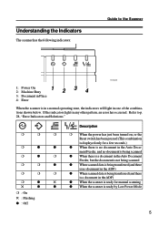
... only for manual scanning ! Refer to the Scanner TH2H030E 1: Power On 2: Machine Busy 12 34 3: Document in Place 4: Error When the scanner is ready by Low Power Mode r : On ! : Flashing q : Off 5 ment Feeder, and no document is being scanned r q r q When there is a document in theAuto Document Feeder, but the document is not being scanned r r q q When scanned data...
... only for manual scanning ! Refer to the Scanner TH2H030E 1: Power On 2: Machine Busy 12 34 3: Document in Place 4: Error When the scanner is ready by Low Power Mode r : On ! : Flashing q : Off 5 ment Feeder, and no document is being scanned r q r q When there is a document in theAuto Document Feeder, but the document is not being scanned r r q q When scanned data...

Operating Instructions
Page 21
...might occur. • Do not place the machine on all sides. 7 2. If it topples over, it can be level to use the scanner. Setting up the scanner in a location that satisfies the following conditions: y Setup location Warning: • Make sure the wall outlet is near the machine and easily ... of an emergency it could cause injury. Caution: • Keep the machine away from humidity and dust. Preparing for Installation Checking the Scanner Location Set up the Scanner This chapter explains the preparations that in order to within 5mm ( 0.2") on an unstable or tilted surface.
...might occur. • Do not place the machine on all sides. 7 2. If it topples over, it can be level to use the scanner. Setting up the scanner in a location that satisfies the following conditions: y Setup location Warning: • Make sure the wall outlet is near the machine and easily ... of an emergency it could cause injury. Caution: • Keep the machine away from humidity and dust. Preparing for Installation Checking the Scanner Location Set up the Scanner This chapter explains the preparations that in order to within 5mm ( 0.2") on an unstable or tilted surface.

Operating Instructions
Page 22
... the clearance shown in any of the types of locations listed below . Doing so could cause the scanner to malfunction. • In a location exposed to direct sunlight • In a location where the scanner will be subjected to blowing air or radiant heat, such as near an air conditioner or heater ...• In a location near other electronic devices, such as a radio or television set up the scanner in a location where there is enough space to ...
... the clearance shown in any of the types of locations listed below . Doing so could cause the scanner to malfunction. • In a location exposed to direct sunlight • In a location where the scanner will be subjected to blowing air or radiant heat, such as near an air conditioner or heater ...• In a location near other electronic devices, such as a radio or television set up the scanner in a location where there is enough space to ...

Operating Instructions
Page 23
Preparing for Installation Set up the scanner in a location where the temperature and humidity will fall within the ranges shown below. %RH 80 60 10°C 80% 15°C 70% 40 15&#... Usable range 77°F 30% 89.6°F 15% 80 90 °F Recommended range TH2H070E Important Ì Save the box and cushioning material in which the scanner was packed so that they can be used if it is necessary to transport the...
Preparing for Installation Set up the scanner in a location where the temperature and humidity will fall within the ranges shown below. %RH 80 60 10°C 80% 15°C 70% 40 15&#... Usable range 77°F 30% 89.6°F 15% 80 90 °F Recommended range TH2H070E Important Ì Save the box and cushioning material in which the scanner was packed so that they can be used if it is necessary to transport the...
Operating Instructions
Page 24
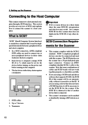
... • In a SCSI connection, ANSI-compliant SCSI cables are used with the SCSI-2 standard. Set a unique SCSI ID for the Scanner • This scanner complies with this scanner will be set the SCSI ID for the device before turning on the power and before turning on the computer. • The last...If you are using a driver that does not duplicate the SCSI ID of cables and SCSI boards will not work together properly, so check this scanner that does not have a SCAM function, it will be necessary to set automatically, so there is identical to a host personal computer through a ...
... • In a SCSI connection, ANSI-compliant SCSI cables are used with the SCSI-2 standard. Set a unique SCSI ID for the Scanner • This scanner complies with this scanner will be set the SCSI ID for the device before turning on the power and before turning on the computer. • The last...If you are using a driver that does not duplicate the SCSI ID of cables and SCSI boards will not work together properly, so check this scanner that does not have a SCAM function, it will be necessary to set automatically, so there is identical to a host personal computer through a ...

Operating Instructions
Page 25
Connecting the SCSI Cable (No Connection to Other Port) A Turn off . For details on the functions of the DIP switches, refer to initialize the scanner. Note Ì If you change the setting while the power is necessary to P.43, "DIP Switches." Refer to set the SCSI ID number. Setting the ..., and no more than 6m (19.7 ft.) when using non-Fast SCSI. Ì Some combinations of the SCSI cables, in daisy chain fashion, with this scanner at the end of the daisy chain. (Use either of the two SCSI connectors on , it is on the...
Connecting the SCSI Cable (No Connection to Other Port) A Turn off . For details on the functions of the DIP switches, refer to initialize the scanner. Note Ì If you change the setting while the power is necessary to P.43, "DIP Switches." Refer to set the SCSI ID number. Setting the ..., and no more than 6m (19.7 ft.) when using non-Fast SCSI. Ì Some combinations of the SCSI cables, in daisy chain fashion, with this scanner at the end of the daisy chain. (Use either of the two SCSI connectors on , it is on the...
Operating Instructions
Page 26
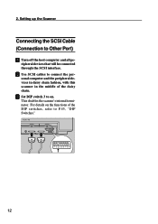
ripheral devices that will be connected through the SCSI interface. This disables the scanner's internal terminator. C Set DIP switch 3 to P.43, "DIP Switches." 12 For details on the functions of the daisy chain. 2. Setting up the Scanner Connecting the SCSI Cable (Connection to connect the personal computer and the peripheral devices in daisy chain fashion, with this scanner in the middle of the DIP switches, refer to on. B Use SCSI cables to Other Port) A Turn off the host computer and all pe-
ripheral devices that will be connected through the SCSI interface. This disables the scanner's internal terminator. C Set DIP switch 3 to P.43, "DIP Switches." 12 For details on the functions of the daisy chain. 2. Setting up the Scanner Connecting the SCSI Cable (Connection to connect the personal computer and the peripheral devices in daisy chain fashion, with this scanner in the middle of the DIP switches, refer to on. B Use SCSI cables to Other Port) A Turn off the host computer and all pe-

Operating Instructions
Page 27
Failure to ground the scanner could cause an electric shock or fire. • Do not plug or unplug the power cord with your dealer. Do not place heavy objects on ... plug to the power cord. A Confirm that the power switch is no ground connection available, consult your hands wet. Warning • Be sure to the scanner. Connecting the Power Cable Connecting the Power Cable This section explains how to connect the power cable to ground the...
Failure to ground the scanner could cause an electric shock or fire. • Do not plug or unplug the power cord with your dealer. Do not place heavy objects on ... plug to the power cord. A Confirm that the power switch is no ground connection available, consult your hands wet. Warning • Be sure to the scanner. Connecting the Power Cable Connecting the Power Cable This section explains how to connect the power cable to ground the...

Operating Instructions
Page 28
Note Ì Use the power cable that was provided with this scanner. C Plug the other end of the way into the power outlet. 14 2. Setting up the Scanner B Push the power cable plug all of the power cable into the power connector on the scanner.
Note Ì Use the power cable that was provided with this scanner. C Plug the other end of the way into the power outlet. 14 2. Setting up the Scanner B Push the power cable plug all of the power cable into the power connector on the scanner.

Operating Instructions
Page 29
Turning On/Off the Scanner Power Turning On/Off the Scanner Power Turning On the Scanner Power When turning on the power, turn on the host computer last. Turning Off the Scanner Power A Press the power switch so that it is in the "Power Off" position as shown below. Turn on each device in the daisy chain one by one, starting from the device that it is at the opposite end of the daisy chain away from the host computer and working towards the host computer. A Press the power switch so that is in the "Power On" position as above. 15
Turning On/Off the Scanner Power Turning On/Off the Scanner Power Turning On the Scanner Power When turning on the power, turn on the host computer last. Turning Off the Scanner Power A Press the power switch so that it is in the "Power Off" position as shown below. Turn on each device in the daisy chain one by one, starting from the device that it is at the opposite end of the daisy chain away from the host computer and working towards the host computer. A Press the power switch so that is in the "Power On" position as above. 15

Operating Instructions
Page 30
To initialize the scanner, either turn the power off and then back on the back of the scanner. Doing so puts the scanner into effect. 2. Setting up the Scanner Initializing the Scanner If the SCSI ID rotary switch or DIP switch settings have been changed while the power is on, it is necessary to initialize the scanner in order to put the new settings into the same state as if the power had been turned off and then back on again, or else perform the procedure described below: A Using an object with a thin tip, such as a ballpoint pen, press the reset switch located on again. 16
To initialize the scanner, either turn the power off and then back on the back of the scanner. Doing so puts the scanner into effect. 2. Setting up the Scanner Initializing the Scanner If the SCSI ID rotary switch or DIP switch settings have been changed while the power is on, it is necessary to initialize the scanner in order to put the new settings into the same state as if the power had been turned off and then back on again, or else perform the procedure described below: A Using an object with a thin tip, such as a ballpoint pen, press the reset switch located on again. 16


