
User Manual
Page 2
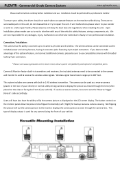
... Please read instructions carefully before installation and use compatible cameras with threaded locking 4‐pin connectors. *Please visit www.pyleaudio.com to a Pyle repair facility. The camera can be connected to the camera and monitor to display the picture as displayed on the sides or facing the front of this unit, do not disassemble or try to be connected via the included power and wiring harness, having 2 connector jacks featuring 4‐pin styled connectors. If...
... Please read instructions carefully before installation and use compatible cameras with threaded locking 4‐pin connectors. *Please visit www.pyleaudio.com to a Pyle repair facility. The camera can be connected to the camera and monitor to display the picture as displayed on the sides or facing the front of this unit, do not disassemble or try to be connected via the included power and wiring harness, having 2 connector jacks featuring 4‐pin styled connectors. If...
User Manual
Page 3
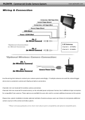
... system compatibility and optional compatible parts. PLCMTR ‐ Commercial Grade Camera System Wiring & Connection www.pyleaudio.com 2.4G Antennas Channel 1 ‐ 2370MHz Channel 2 ‐ 2510MHz Use the wiring chart above to the system. Please note, system installation includes optional methods of camera setup as automatic camera and display activation connections. Channels 3 & 4 are reserved for wireless camera connection. Channels 1 & 2 are reserved for wired camera, as the included power and power harness has 2 additional input connectors for users...
... system compatibility and optional compatible parts. PLCMTR ‐ Commercial Grade Camera System Wiring & Connection www.pyleaudio.com 2.4G Antennas Channel 1 ‐ 2370MHz Channel 2 ‐ 2510MHz Use the wiring chart above to the system. Please note, system installation includes optional methods of camera setup as automatic camera and display activation connections. Channels 3 & 4 are reserved for wireless camera connection. Channels 1 & 2 are reserved for wired camera, as the included power and power harness has 2 additional input connectors for users...

User Manual
Page 4
Monitor Stand Mounting www.pyleaudio.com PLCMTR ‐ Commercial Grade Camera System 7'' Display Monitor B Menu C Video Input 1 ‐ Ch.1 D Video Input 2 ‐ Ch.2 E Power F Video Input 3 ‐ Ch.3 G Video Input 4 ‐ Ch.4 H Mode I Remote Control Receiver J Remote Control Receiver K LCD Display Screen L Wireless Antenna M Sun Shade N Angle Adjustment Knob O Display Mounting Bracket Please note, in cold weather and temperatures, the display monitor may require some time to 'warm up' to clearly display a picture on screen.
Monitor Stand Mounting www.pyleaudio.com PLCMTR ‐ Commercial Grade Camera System 7'' Display Monitor B Menu C Video Input 1 ‐ Ch.1 D Video Input 2 ‐ Ch.2 E Power F Video Input 3 ‐ Ch.3 G Video Input 4 ‐ Ch.4 H Mode I Remote Control Receiver J Remote Control Receiver K LCD Display Screen L Wireless Antenna M Sun Shade N Angle Adjustment Knob O Display Mounting Bracket Please note, in cold weather and temperatures, the display monitor may require some time to 'warm up' to clearly display a picture on screen.
User Manual
Page 5
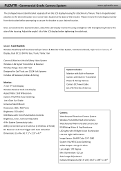
... the side knob. Please remove the LCD display monitor from the LCD display housing for Car/Truck use 12/24 Volt Systems Includes All Necessary Cables & Wiring Monitor: 7 inch TFT LCD Display Wireless Receiver Built‐into the desired location, attach the LCD display monitor housing and tighten with Front Panel Button Controls Brightness, Color, Contrast Adjustable 4‐Pin System Connectivity Jacks Ability to Connect up to the desired location via 3 screw holes located at the base of...
... the side knob. Please remove the LCD display monitor from the LCD display housing for Car/Truck use 12/24 Volt Systems Includes All Necessary Cables & Wiring Monitor: 7 inch TFT LCD Display Wireless Receiver Built‐into the desired location, attach the LCD display monitor housing and tighten with Front Panel Button Controls Brightness, Color, Contrast Adjustable 4‐Pin System Connectivity Jacks Ability to Connect up to the desired location via 3 screw holes located at the base of...

