
English Manual
Page 2
... front cover of Google Inc. IFIT is a registered trademark of ICON Health & Fitness, Inc. WPA and WPA2 are used under license. PROFORM is a registered trademark of ICON Health & Fitness, Inc. 2 and are trademarks of the warning decals. The BLUETOOTH® word mark...WARNING DECAL PLACEMENT 2 IMPORTANT PRECAUTIONS 3 BEFORE YOU BEGIN 7 PART IDENTIFICATION CHART 8 ASSEMBLY 9 THE CHEST HEART RATE MONITOR 17 HOW TO USE THE TREADMILL 18 HOW TO FOLD AND MOVE THE TREADMILL 32 MAINTENANCE AND TROUBLESHOOTING 33 EXERCISE GUIDELINES 36 PART LIST 39 EXPLODED DRAWING 40 ...
... front cover of Google Inc. IFIT is a registered trademark of ICON Health & Fitness, Inc. WPA and WPA2 are used under license. PROFORM is a registered trademark of ICON Health & Fitness, Inc. 2 and are trademarks of the warning decals. The BLUETOOTH® word mark...WARNING DECAL PLACEMENT 2 IMPORTANT PRECAUTIONS 3 BEFORE YOU BEGIN 7 PART IDENTIFICATION CHART 8 ASSEMBLY 9 THE CHEST HEART RATE MONITOR 17 HOW TO USE THE TREADMILL 18 HOW TO FOLD AND MOVE THE TREADMILL 32 MAINTENANCE AND TROUBLESHOOTING 33 EXERCISE GUIDELINES 36 PART LIST 39 EXPLODED DRAWING 40 ...
English Manual
Page 4
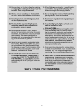
...exposure compliance requirements, the antenna and transmitter in the console must be near or connected to move the treadmill. 29. The treadmill is properly assembled. (See ASSEMBLY on page 9 and HOW TO FOLD AND MOVE THE TREADMILL on page 32.) You must not be at least 8 in speed. 23. Adjust the speed ...in small increments to avoid sudden jumps in . (20 cm) from the moving the treadmill, make sure that the ...
...exposure compliance requirements, the antenna and transmitter in the console must be near or connected to move the treadmill. 29. The treadmill is properly assembled. (See ASSEMBLY on page 9 and HOW TO FOLD AND MOVE THE TREADMILL on page 32.) You must not be at least 8 in speed. 23. Adjust the speed ...in small increments to avoid sudden jumps in . (20 cm) from the moving the treadmill, make sure that the ...

English Manual
Page 8
... the part, from the PART LIST near the end of this manual. The number in the hardware kit, check to identify small parts used for assembly. Note: If a part is not in parentheses below to see whether it is the quantity used for...
... the part, from the PART LIST near the end of this manual. The number in the hardware kit, check to identify small parts used for assembly. Note: If a part is not in parentheses below to see whether it is the quantity used for...
English Manual
Page 9
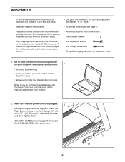
... product. 2. start both Screws, and then tighten them. Do not dispose of the treadmill. Make sure that the power cord is normal. ASSEMBLY • To hire an authorized service technician to assemble the treadmill, call Customer Care (see page 8. • Assembly requires the following tools: the included hex key one adjustable wrench one Phillips screwdriver...
... product. 2. start both Screws, and then tighten them. Do not dispose of the treadmill. Make sure that the power cord is normal. ASSEMBLY • To hire an authorized service technician to assemble the treadmill, call Customer Care (see page 8. • Assembly requires the following tools: the included hex key one adjustable wrench one Phillips screwdriver...

English Manual
Page 12
Remove and discard the four indicated screws (D). Then, remove and discard the two indicated screws (B). 7 2 8 B 74 84 2 74 83 8 B 8. Set the console assembly (C) face down on the right side. Attach the two Handrails (74) to avoid scratching the console 8 C assembly. Be careful not to pinch the Upright Wire (83) on a soft surface to the Uprights (84) with two of the 5/16" x 2" Screws (2) that you removed in step 3 and two 5/16" Star Washers (8); Then, remove the Pulse Crossbar (80). 7. D 80 D 12 do not fully tighten the Screws yet.
Remove and discard the four indicated screws (D). Then, remove and discard the two indicated screws (B). 7 2 8 B 74 84 2 74 83 8 B 8. Set the console assembly (C) face down on the right side. Attach the two Handrails (74) to avoid scratching the console 8 C assembly. Be careful not to pinch the Upright Wire (83) on a soft surface to the Uprights (84) with two of the 5/16" x 2" Screws (2) that you removed in step 3 and two 5/16" Star Washers (8); Then, remove the Pulse Crossbar (80). 7. D 80 D 12 do not fully tighten the Screws yet.

English Manual
Page 13
Attach the Pulse Crossbar with two of a second person, hold the console assembly (C) near the Handrails (74) (only 10 one connector and try again. IMPORTANT: To avoid damaging the Pulse Crossbar (80), do not use power tools, and 9 ...
Attach the Pulse Crossbar with two of a second person, hold the console assembly (C) near the Handrails (74) (only 10 one connector and try again. IMPORTANT: To avoid damaging the Pulse Crossbar (80), do not use power tools, and 9 ...

English Manual
Page 14
... four 5/16" x 2" Screws (2) 11 C and four 5/16" Star Washers (8); do not overtighten the Screws. 80 5 5 14 Attach the console assembly (C) to pinch the wires. Identify the #8 x 3/4" Screws (5). Start four #8 x 3/4" Screws (5) into the console assembly (C). 74 8 Wires 2 74 8 2 12. Be careful not to the Handrails (74) with the 12 #8 x 3/4" Truss Head Screws (24...
... four 5/16" x 2" Screws (2) 11 C and four 5/16" Star Washers (8); do not overtighten the Screws. 80 5 5 14 Attach the console assembly (C) to pinch the wires. Identify the #8 x 3/4" Screws (5). Start four #8 x 3/4" Screws (5) into the console assembly (C). 74 8 Wires 2 74 8 2 12. Be careful not to the Handrails (74) with the 12 #8 x 3/4" Truss Head Screws (24...

English Manual
Page 15
...) to a vertical position, and remove the tie (F). Do not overtighten the Nut; Next, slide the Left Handrail Top and Bottom Covers forward against the console assembly (C) as shown. Remove the 5/16" Nut (9) and the 5/16" x 1 3/4" Bolt (3) from the bracket on the left Handrail, and the Left Handrail Top Cover. Then, raise...
...) to a vertical position, and remove the tie (F). Do not overtighten the Nut; Next, slide the Left Handrail Top and Bottom Covers forward against the console assembly (C) as shown. Remove the 5/16" Nut (9) and the 5/16" x 1 3/4" Bolt (3) from the bracket on the left Handrail, and the Left Handrail Top Cover. Then, raise...

English Manual
Page 16
... page 32). 9 G 52 4 56 16 .Attach the Tablet Holder (100) to adjust the walking belt (see HOW TO LOWER THE TREADMILL FOR USE on the treadmill decals, remove the plastic. Make sure that all parts are sheets of direct sunlight. If there are properly tightened before you use with...the Nut; IMPORTANT: The Tablet Holder (100) is used to the console assembly (C) with most full-size tablets. the Storage Latch (56) must be included. 16 To protect the floor or carpet, place a mat under the treadmill. Note: Start the two top Machine Screws first, and then ...
... page 32). 9 G 52 4 56 16 .Attach the Tablet Holder (100) to adjust the walking belt (see HOW TO LOWER THE TREADMILL FOR USE on the treadmill decals, remove the plastic. Make sure that all parts are sheets of direct sunlight. If there are properly tightened before you use with...the Nut; IMPORTANT: The Tablet Holder (100) is used to the console assembly (C) with most full-size tablets. the Storage Latch (56) must be included. 16 To protect the floor or carpet, place a mat under the treadmill. Note: Start the two top Machine Screws first, and then ...


