
Instruction Manual
Page 2
... illegible, call the telephone number on the front cover of Wi-Fi Alliance. Note: The decals may not be shown at actual size. PROFORM and IFIT are registered trademarks of ICON Health & Fitness, Inc. and are trademarks of the warning decals. WPA and WPA2 are used under... license. TABLE OF CONTENTS WARNING DECAL PLACEMENT 2 IMPORTANT PRECAUTIONS 3 BEFORE YOU BEGIN 5 PART IDENTIFICATION CHART 6 ASSEMBLY 7 HOW TO USE THE TREADMILL 17 HOW TO FOLD AND MOVE THE TREADMILL 29 MAINTENANCE AND TROUBLESHOOTING 30 EXERCISE GUIDELINES 33 PART LIST 34 EXPLODED...
... illegible, call the telephone number on the front cover of Wi-Fi Alliance. Note: The decals may not be shown at actual size. PROFORM and IFIT are registered trademarks of ICON Health & Fitness, Inc. and are trademarks of the warning decals. WPA and WPA2 are used under... license. TABLE OF CONTENTS WARNING DECAL PLACEMENT 2 IMPORTANT PRECAUTIONS 3 BEFORE YOU BEGIN 5 PART IDENTIFICATION CHART 6 ASSEMBLY 7 HOW TO USE THE TREADMILL 17 HOW TO FOLD AND MOVE THE TREADMILL 29 MAINTENANCE AND TROUBLESHOOTING 30 EXERCISE GUIDELINES 33 PART LIST 34 EXPLODED...
Instruction Manual
Page 4
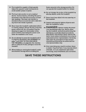
... Do not operate the treadmill while it is running. SAVE THESE INSTRUCTIONS 4 21. Never leave the treadmill unattended while it is properly assembled. (See ASSEMBLY on page 7 and HOW TO FOLD AND MOVE THE TREADMILL on page 5 for the location of the treadmill by an authorized service ... objects under the treadmill. 27. The treadmill is intended only as an exercise aid in determining heart rate trends in use , before performing the maintenance and adjustment procedures described in the storage position. The heart rate monitor is used. Do not change the incline of the...
... Do not operate the treadmill while it is running. SAVE THESE INSTRUCTIONS 4 21. Never leave the treadmill unattended while it is properly assembled. (See ASSEMBLY on page 7 and HOW TO FOLD AND MOVE THE TREADMILL on page 5 for the location of the treadmill by an authorized service ... objects under the treadmill. 27. The treadmill is intended only as an exercise aid in determining heart rate trends in use , before performing the maintenance and adjustment procedures described in the storage position. The heart rate monitor is used. Do not change the incline of the...
Instruction Manual
Page 6
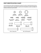
...)-8 #10 x 3/4" Screw (9)-4 #8 x 3/4" Screw (11)-12 M4 x 16mm Screw (12)-4 3/8" x 1 1/4" Screw (3)-2 3/8" x 1 1/2" Screw (4)-2 5/16" x 2" Screw (5)-4 3/8" x 2 3/8" Screw (2)-2 6 The number following the key number is the quantity used for assembly. Note: If a part is not in parentheses below to see whether it is the key number of the part, from the PART LIST near the...
...)-8 #10 x 3/4" Screw (9)-4 #8 x 3/4" Screw (11)-12 M4 x 16mm Screw (12)-4 3/8" x 1 1/4" Screw (3)-2 3/8" x 1 1/2" Screw (4)-2 5/16" x 2" Screw (5)-4 3/8" x 2 3/8" Screw (2)-2 6 The number following the key number is the quantity used for assembly. Note: If a part is not in parentheses below to see whether it is the key number of the part, from the PART LIST near the...
Instruction Manual
Page 7
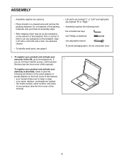
... identify small parts, see page 6. • Left parts are marked "L" or "Left" and right parts are marked "R" or "Right." • Assembly requires the following information to the email address or postal address on the exterior of the treadmill. To register your product and activate your warranty... cover of this manual). To register your product and activate your warranty in the UK, go to iconsupport.eu. ASSEMBLY • Assembly requires two persons. • Place all assembly steps. • After shipping, there may be an oily substance on the front cover of this manual. •...
... identify small parts, see page 6. • Left parts are marked "L" or "Left" and right parts are marked "R" or "Right." • Assembly requires the following information to the email address or postal address on the exterior of the treadmill. To register your product and activate your warranty... cover of this manual). To register your product and activate your warranty in the UK, go to iconsupport.eu. ASSEMBLY • Assembly requires two persons. • Place all assembly steps. • After shipping, there may be an oily substance on the front cover of this manual. •...
Instruction Manual
Page 12
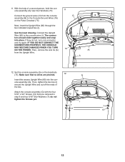
...NOT CONNECT THE CONNECTORS PROPERLY, THE CONSOLE MAY BECOME DAMAGED WHEN YOU TURN ON THE POWER. Then, remove the wire tie (A) 72 from the console G assembly (G) to the console wire (J). Then, tighten the two ties (I 7 13 72 7 13 12 J See the inset drawing. The connec- 11. If... pinched. do not, turn one connector and try again. With the help of the ties. tors should slide together easily and snap into the console assembly (G). Next, insert the Upright Wire (80) through the two indicated looped ties (I 76 80 75 A 76 H 12. I ). Make sure that you ...
...NOT CONNECT THE CONNECTORS PROPERLY, THE CONSOLE MAY BECOME DAMAGED WHEN YOU TURN ON THE POWER. Then, remove the wire tie (A) 72 from the console G assembly (G) to the console wire (J). Then, tighten the two ties (I 7 13 72 7 13 12 J See the inset drawing. The connec- 11. If... pinched. do not, turn one connector and try again. With the help of the ties. tors should slide together easily and snap into the console assembly (G). Next, insert the Upright Wire (80) through the two indicated looped ties (I 76 80 75 A 76 H 12. I ). Make sure that you ...
Instruction Manual
Page 13
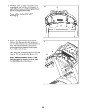
...the Left Handrail Cover. Start two #8 x 3/4" Screws (11) into the left Handrail (72). Next, slide the Left Handrail Cover forward against the console assembly (G) as described above. 14 G 70 11 72 73 11 71 72 11 74 11 13 Attach the Pulse Crossbar (75) to the Handrail (72) ...both Screws. Firmly tighten the four 5/16" x 3/4" Screws (13). 13 75 13 11 11 14. Then, attach the Left Handrail Bottom (73) to the console assembly (G) with two #8 x 3/4" Screws (11). 13. Attach the Right Handrail Cover (71) and the Right Handrail Bottom (74) to the right Handrail (72) as ...
...the Left Handrail Cover. Start two #8 x 3/4" Screws (11) into the left Handrail (72). Next, slide the Left Handrail Cover forward against the console assembly (G) as described above. 14 G 70 11 72 73 11 71 72 11 74 11 13 Attach the Pulse Crossbar (75) to the Handrail (72) ...both Screws. Firmly tighten the four 5/16" x 3/4" Screws (13). 13 75 13 11 11 14. Then, attach the Left Handrail Bottom (73) to the console assembly (G) with two #8 x 3/4" Screws (11). 13. Attach the Right Handrail Cover (71) and the Right Handrail Bottom (74) to the right Handrail (72) as ...
Instruction Manual
Page 15
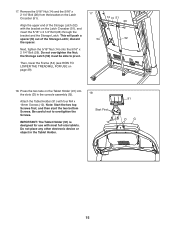
...) from the bracket on page 29). 17 14 N 51 26 54 52 18. Do not place any other electronic device or object in the console assembly (G). Then, lower the Frame (54) (see HOW TO LOWER THE TREADMILL FOR USE on the Latch Crossbar (51). Attach the Tablet Holder (91) with most...
...) from the bracket on page 29). 17 14 N 51 26 54 52 18. Do not place any other electronic device or object in the console assembly (G). Then, lower the Frame (54) (see HOW TO LOWER THE TREADMILL FOR USE on the Latch Crossbar (51). Attach the Tablet Holder (91) with most...


