
Uk Manual
Page 5
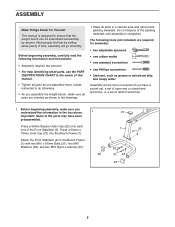
... area and remove the packing materials. Assembly will go smoothly. Press a 50mm Square Outer Cap (22) onto each end of the packing materials until assembly is designed to ensure that by anyone. Attach the Front Stabiliser (2) to the Bench Frame (1) with two M10 x 67mm Bolts (31), two M10... CHART in the center of this manual. • Tighten all parts as grease or petroleum jelly, and soapy water. Press a 50mm x 75mm Inner Cap (21) into the Bench Frame (1). Before beginning assembly, carefully read the following tools (not included) are oriented as shown in the drawings. •...
... area and remove the packing materials. Assembly will go smoothly. Press a 50mm Square Outer Cap (22) onto each end of the packing materials until assembly is designed to ensure that by anyone. Attach the Front Stabiliser (2) to the Bench Frame (1) with two M10 x 67mm Bolts (31), two M10... CHART in the center of this manual. • Tighten all parts as grease or petroleum jelly, and soapy water. Press a 50mm x 75mm Inner Cap (21) into the Bench Frame (1). Before beginning assembly, carefully read the following tools (not included) are oriented as shown in the drawings. •...
Uk Manual
Page 6
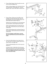
... 7 19 27 Lubricate 37 6 Do not overtighten the Nylon Locknut; Press a 50mm Square Outer Cap (22) onto each 2 end of the Seat Frame (5). Press four 8mm Bushings (14) into the weight tube. Attach the Leg Lever (4) to the Bench Frame (1) with the Bolt and an M10 Nylon Locknut (33). Attach... M10 x 45mm Adjustment Knob (28). the Leg Lever must be able to the Seat Frame (5) with grease. Press two 25mm Round Inner Caps (19) into the indicated holes in the Seat Frame and the Bench Frame (1). Attach the Leg Lever Bracket (7) to pivot easily. 1 22 31 32 32 22 33 3 14 ...
... 7 19 27 Lubricate 37 6 Do not overtighten the Nylon Locknut; Press a 50mm Square Outer Cap (22) onto each 2 end of the Seat Frame (5). Press four 8mm Bushings (14) into the weight tube. Attach the Leg Lever (4) to the Bench Frame (1) with the Bolt and an M10 Nylon Locknut (33). Attach... M10 x 45mm Adjustment Knob (28). the Leg Lever must be able to the Seat Frame (5) with grease. Press two 25mm Round Inner Caps (19) into the indicated holes in the Seat Frame and the Bench Frame (1). Attach the Leg Lever Bracket (7) to pivot easily. 1 22 31 32 32 22 33 3 14 ...
Uk Manual
Page 7
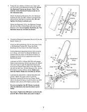
... (35) with four M6 x 50mm Bolts (23) and four M6 Washers (34). Attach the lower holes in the Seat Frame (5). Press the four 20mm x 40mm Inner Caps (12) into the Bench Frame (1). Press two 8mm Bushings into the lower holes in step 5. 5 10 12 34 23 24 Indents 25 24 8 12 23 9 34... 6 10 32 33 14 8 Large Hole 36 4 15 14 5 9 Adjustment Holes 32 Lubricate 14 35 Warning Decal 13 1 14 15 7 The Backrest must be on the Bench Frame...
... (35) with four M6 x 50mm Bolts (23) and four M6 Washers (34). Attach the lower holes in the Seat Frame (5). Press the four 20mm x 40mm Inner Caps (12) into the Bench Frame (1). Press two 8mm Bushings into the lower holes in step 5. 5 10 12 34 23 24 Indents 25 24 8 12 23 9 34... 6 10 32 33 14 8 Large Hole 36 4 15 14 5 9 Adjustment Holes 32 Lubricate 14 35 Warning Decal 13 1 14 15 7 The Backrest must be on the Bench Frame...
Uk Manual
Page 8
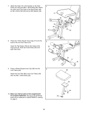
Press a 45mm Square Inner Cap (29) into the holes in ADJUSTMENTS, starting on the Seat 7 Frame (5) using two M6 x 16mm Bolts (26). The use of the ... Foam Pads (18) onto each Pad Tube. 8 18 16 4 17 9. Attach the Curl Pad (38) to the bracket on page 9. 26 29 8 Press four 19mm Round Inner Caps (17) into the ends of the weight bench are properly tightened. Make sure that all remaining parts will be explained in the Leg Lever (4).
Press a 45mm Square Inner Cap (29) into the holes in ADJUSTMENTS, starting on the Seat 7 Frame (5) using two M6 x 16mm Bolts (26). The use of the ... Foam Pads (18) onto each Pad Tube. 8 18 16 4 17 9. Attach the Curl Pad (38) to the bracket on page 9. 26 29 8 Press four 19mm Round Inner Caps (17) into the ends of the weight bench are properly tightened. Make sure that all remaining parts will be explained in the Leg Lever (4).


