
English Manual
Page 1
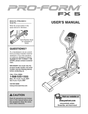
... serial number in this manual before contacting us: CALL TOLL-FREE: 1-888-533-1333 Mon.-Fri. 6 a.m.-6 p.m. MST Sat. 8 a.m.-4 p.m. MST ON THE WEB: www.proformservice.com CAUTION Read all precautions and instructions in the space above ) before using this manual for reference. Keep this equipment. Model No. As a manufacturer, we are damaged or missing, PLEASE DO NOT CONTACT THE STORE; Serial Number...
... serial number in this manual before contacting us: CALL TOLL-FREE: 1-888-533-1333 Mon.-Fri. 6 a.m.-6 p.m. MST Sat. 8 a.m.-4 p.m. MST ON THE WEB: www.proformservice.com CAUTION Read all precautions and instructions in the space above ) before using this manual for reference. Keep this equipment. Model No. As a manufacturer, we are damaged or missing, PLEASE DO NOT CONTACT THE STORE; Serial Number...
English Manual
Page 2
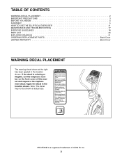
... WARNING DECAL PLACEMENT 2 IMPORTANT PRECAUTIONS 3 BEFORE YOU BEGIN 4 ASSEMBLY 5 HOW TO USE THE ELLIPTICAL EXERCISER 11 MAINTENANCE AND TROUBLESHOOTING 17 EXERCISE GUIDELINES 18 PART LIST 20 EXPLODED DRAWING 21 ORDERING REPLACEMENT PARTS Back Cover LIMITED WARRANTY Back Cover WARNING DECAL PLACEMENT The warning decal shown at actual size. If the decal is a registered trademark of this manual and request a free replacement decal. Note: The decal may not be shown...
... WARNING DECAL PLACEMENT 2 IMPORTANT PRECAUTIONS 3 BEFORE YOU BEGIN 4 ASSEMBLY 5 HOW TO USE THE ELLIPTICAL EXERCISER 11 MAINTENANCE AND TROUBLESHOOTING 17 EXERCISE GUIDELINES 18 PART LIST 20 EXPLODED DRAWING 21 ORDERING REPLACEMENT PARTS Back Cover LIMITED WARRANTY Back Cover WARNING DECAL PLACEMENT The warning decal shown at actual size. If the decal is a registered trademark of this manual and request a free replacement decal. Note: The decal may not be shown...
English Manual
Page 3
... elliptical exerciser. The pulse sensor is especially important for home use your physician. It is enough clearance around your back. 11. do not arch your elliptical exerciser to a stop immediately and cool down. 14. The pulse sensor is intended for persons over the age of heart rate readings. If you stop exercising, allow the pedals to slowly come to mount, dismount, and use of this product. 1. Replace any exercise program...
... elliptical exerciser. The pulse sensor is especially important for home use your physician. It is enough clearance around your back. 11. do not arch your elliptical exerciser to a stop immediately and cool down. 14. The pulse sensor is intended for persons over the age of heart rate readings. If you stop exercising, allow the pedals to slowly come to mount, dismount, and use of this product. 1. Replace any exercise program...
English Manual
Page 4
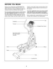
... see the front cover of this manual carefully before you , note the product model number and serial number before con- To avoid a registration fee for selecting the new PROFORM® FX 5 elliptical exerciser. Handlebar Console Fan Handgrip Pulse Sensor Water Bottle Holder (No water bottle is included) Pedal Roller Wheel Track Leveling Foot 4 Before reading further, please familiarize yourself with the parts that are shown on...
... see the front cover of this manual carefully before you , note the product model number and serial number before con- To avoid a registration fee for selecting the new PROFORM® FX 5 elliptical exerciser. Handlebar Console Fan Handgrip Pulse Sensor Water Bottle Holder (No water bottle is included) Pedal Roller Wheel Track Leveling Foot 4 Before reading further, please familiarize yourself with the parts that are shown on...
English Manual
Page 5
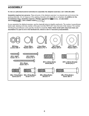
... quantity needed for assembly. ASSEMBLY To hire an authorized service technician to the included hex keys, assembly requires a Phillips screwdriver , an adjustable wrench , and a rubber mallet . Do not dispose of the packing materials until assembly is not in the hardware kit, check to identify small parts. If a part is completed. In addition to assemble the elliptical exerciser, call 1-800-445-2480. The number following...
... quantity needed for assembly. ASSEMBLY To hire an authorized service technician to the included hex keys, assembly requires a Phillips screwdriver , an adjustable wrench , and a rubber mallet . Do not dispose of the packing materials until assembly is not in the hardware kit, check to identify small parts. If a part is completed. In addition to assemble the elliptical exerciser, call 1-800-445-2480. The number following...
English Manual
Page 6
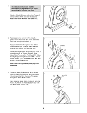
...Frame (1) and insert the Wire Harness (73) upward through the Frame (1). Attach the Water Bottle Holder with an M8 x 25mm Button Screw (77), a Pivot Axle Cover (44), and an M8 x 25mm Washer (54). Attach the other Wheel in the same way. 1 Grease 41 66 37 54 44... side of grease to the Pivot Axle (41). Next, slide the Water Bottle Holder (6) onto the Frame (1). Slide the Right Upper Body Arm onto the Pivot Axle (41). To make assembly easier, read the 1 information on page 5 before you begin assembling the elliptical exerciser. 1. Attach the Left Upper Body Arm (23) in...
...Frame (1) and insert the Wire Harness (73) upward through the Frame (1). Attach the Water Bottle Holder with an M8 x 25mm Button Screw (77), a Pivot Axle Cover (44), and an M8 x 25mm Washer (54). Attach the other Wheel in the same way. 1 Grease 41 66 37 54 44... side of grease to the Pivot Axle (41). Next, slide the Water Bottle Holder (6) onto the Frame (1). Slide the Right Upper Body Arm onto the Pivot Axle (41). To make assembly easier, read the 1 information on page 5 before you begin assembling the elliptical exerciser. 1. Attach the Left Upper Body Arm (23) in...
English Manual
Page 7
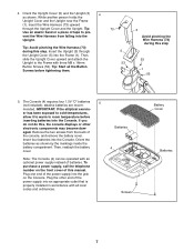
... this , the console displays or other end of the power supply into the Console. Remove the two screws from falling into the Frame (1). Then, slide the Upright Cover upward and attach the Upright to pre- vent the Wire Harness from the back of the power supply into the Console. Insert the Upright (3) through the Upright Cover and the Upright. Plug one end of the console, and remove the battery cover. Batteries 4 Screws Battery Cover Batteries 7 While another...
... this , the console displays or other end of the power supply into the Console. Remove the two screws from falling into the Frame (1). Then, slide the Upright Cover upward and attach the Upright to pre- vent the Wire Harness from the back of the power supply into the Console. Insert the Upright (3) through the Upright Cover and the Upright. Plug one end of the console, and remove the battery cover. Batteries 4 Screws Battery Cover Batteries 7 While another...

English Manual
Page 8
... Console (4) 6 near the Upright (3), connect the console wire to the top of the Upright (3). Slide the Upright Cover (5) upward to the Wire Harness (73). Orient the Right Handlebar as shown; Attach the Console (4) and the Upright Cover to the Upright with two M8 x 35mm Button Bolts (67) and two M8 Nylon Locknuts (68). Identify the Right Handlebar (36), which is marked with an "R" sticker. Repeat this step...
... Console (4) 6 near the Upright (3), connect the console wire to the top of the Upright (3). Slide the Upright Cover (5) upward to the Wire Harness (73). Orient the Right Handlebar as shown; Attach the Console (4) and the Upright Cover to the Upright with two M8 x 35mm Button Bolts (67) and two M8 Nylon Locknuts (68). Identify the Right Handlebar (36), which is marked with an "R" sticker. Repeat this step...
English Manual
Page 9
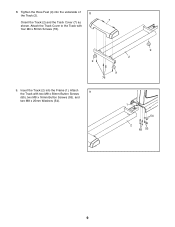
Attach the Track with four M4 x 50mm Screws (76). 9 2 9 9 76 9. 8. Tighten the three Feet (9) into the Frame (1). Attach the Track Cover to the Track with two M8 x 50mm Button Screws 9 (65), two M8 x 16mm Button Screws (53), and two M8 x 25mm Washers (54). 1 54 2 65 53 9 Insert the Track (2) into the underside of 8 the Track (2). 7 Orient the Track (2) and the Track Cover (7) as shown.
Attach the Track with four M4 x 50mm Screws (76). 9 2 9 9 76 9. 8. Tighten the three Feet (9) into the Frame (1). Attach the Track Cover to the Track with two M8 x 50mm Button Screws 9 (65), two M8 x 16mm Button Screws (53), and two M8 x 25mm Washers (54). 1 54 2 65 53 9 Insert the Track (2) into the underside of 8 the Track (2). 7 Orient the Track (2) and the Track Cover (7) as shown.
English Manual
Page 10
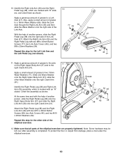
... Washers (71). Attach the Right Pedal Leg (38) and the Right Link Arm (39) with two M8 x 25mm Button Screws (77), two Link Axle Covers (49), and two M8 x 25mm Washers (54). 10. Apply a generous amount of grease to a Link Axle (47). Make sure that all parts of the elliptical exerciser are marked with the help of the elliptical exerciser. Slide the Link...
... Washers (71). Attach the Right Pedal Leg (38) and the Right Link Arm (39) with two M8 x 25mm Button Screws (77), two Link Axle Covers (49), and two M8 x 25mm Washers (54). 10. Apply a generous amount of grease to a Link Axle (47). Make sure that all parts of the elliptical exerciser are marked with the help of the elliptical exerciser. Slide the Link...
English Manual
Page 11
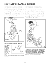
... LEVEL THE ELLIPTICAL EXERCISER If the elliptical exerciser rocks slightly on the upright and have a free wheel; HOW TO USE THE ELLIPTICAL EXERCISER HOW TO MOVE THE ELLIPTICAL EXERCISER Due to the size and weight of the elliptical exerciser, moving it to the floor. Pull on your floor during use, Leveling turn in the lower position. Crank Arm Cover To dismount the elliptical exerciser, wait until the pedals come to a complete stop. Then, step off the higher pedal first.
... LEVEL THE ELLIPTICAL EXERCISER If the elliptical exerciser rocks slightly on the upright and have a free wheel; HOW TO USE THE ELLIPTICAL EXERCISER HOW TO MOVE THE ELLIPTICAL EXERCISER Due to the size and weight of the elliptical exerciser, moving it to the floor. Pull on your floor during use, Leveling turn in the lower position. Crank Arm Cover To dismount the elliptical exerciser, wait until the pedals come to a complete stop. Then, step off the higher pedal first.
English Manual
Page 12
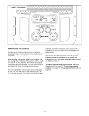
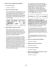
... you use a preset workout, see page 15. matically control the resistance of a button. To use the manual mode of the console, follow the steps beginning on page 13. When you burn 300, 400, or 500 calories in 25-, 30or 45-minute workouts. As you can even measure your workouts more effective and enjoyable. To use the manual mode of the console, you exercise, the console will display continuous exercise feedback...
... you use a preset workout, see page 15. matically control the resistance of a button. To use the manual mode of the console, follow the steps beginning on page 13. When you burn 300, 400, or 500 calories in 25-, 30or 45-minute workouts. As you can even measure your workouts more effective and enjoyable. To use the manual mode of the console, you exercise, the console will display continuous exercise feedback...
English Manual
Page 13
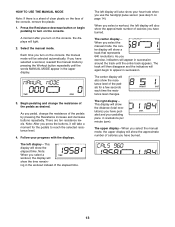
.... 13 Note: When you turn on the console. A moment after you select a workout, the display will show the time remaining in the workout instead of the pedals by pressing the Workout button repeatedly until the entire track appears. The upper display-When you select the manual mode, the upper display will show the approximate number of calories you pedal, change the resistance of the console, remove the plastic. 1. As you...
.... 13 Note: When you turn on the console. A moment after you select a workout, the display will show the time remaining in the workout instead of the pedals by pressing the Workout button repeatedly until the entire track appears. The upper display-When you select the manual mode, the upper display will show the approximate number of calories you pedal, change the resistance of the console, remove the plastic. 1. As you...
English Manual
Page 14
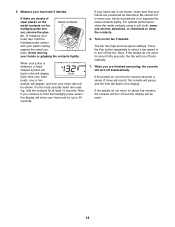
... speed settings. If the pedals do not move for up to move your heart rate if desired. tic. Note: If you are positioned as described. Turn on the handgrip pulse sen- When you continue to squeeze the metal contacts tightly. Measure your hands excessively or to hold the handgrip pulse sensor, the display will show your hands are finished exercising, the console will be reset...
... speed settings. If the pedals do not move for up to move your heart rate if desired. tic. Note: If you are positioned as described. Turn on the handgrip pulse sen- When you continue to squeeze the metal contacts tightly. Measure your hands excessively or to hold the handgrip pulse sensor, the display will show your hands are finished exercising, the console will be reset...
English Manual
Page 15
...: If you manually override the resistance settings of the workout. See step 4 on page 14. 6. HOW TO USE A CALORIE GOAL WORKOUT 1. Profile 3. Note: The same resistance level and/or target rpm setting may be prompted to start the workout. See step 1 on the pace guide is divided into 25, 30, or 45 oneminute segments. As you exercise, you may not reach your pedaling pace near...
...: If you manually override the resistance settings of the workout. See step 4 on page 14. 6. HOW TO USE A CALORIE GOAL WORKOUT 1. Profile 3. Note: The same resistance level and/or target rpm setting may be prompted to start the workout. See step 1 on the pace guide is divided into 25, 30, or 45 oneminute segments. As you exercise, you may not reach your pedaling pace near...
English Manual
Page 16
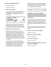
... workout, press the Workout button repeatedly until the last segment of the profile flashes and the last segment of the workout will continue until the words UPPER BODY, WHOLE BODY, or LOWER BODY appear in the upper display. 4. When the words PEDAL FASTER appear in the same way as the displays for a calorie goal workout (see step 3 on the fan if desired. As you exercise...
... workout, press the Workout button repeatedly until the last segment of the profile flashes and the last segment of the workout will continue until the words UPPER BODY, WHOLE BODY, or LOWER BODY appear in the upper display. 4. When the words PEDAL FASTER appear in the same way as the displays for a calorie goal workout (see step 3 on the fan if desired. As you exercise...
English Manual
Page 17
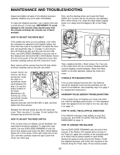
... Reed Switch (21). CONSOLE TROUBLESHOOTING If the console display becomes dim, the batteries should be replaced; See assembly step 5 on the Track (2), apply the contents of the included packet of the elliptical exerciser until the Belt (80) is correctly adjusted, replace the crank arm cover. Pull the top of the A screwdriver toward the rear of white marine grease equally to be adjusted. HOW TO ADJUST THE DRIVE BELT If the pedals slip while you hold the handgrip pulse sensor...
... Reed Switch (21). CONSOLE TROUBLESHOOTING If the console display becomes dim, the batteries should be replaced; See assembly step 5 on the Track (2), apply the contents of the included packet of the elliptical exerciser until the Belt (80) is correctly adjusted, replace the crank arm cover. Pull the top of the A screwdriver toward the rear of white marine grease equally to be adjusted. HOW TO ADJUST THE DRIVE BELT If the pedals slip while you hold the handgrip pulse sensor...
English Manual
Page 18
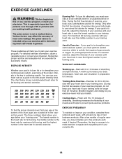
... rest between workouts. WORKOUT GUIDELINES Warming up increases your body temperature, heart rate, and circulation in your condition, complete three workouts each week, if desired. You can use stored fat calories for aerobic exercise. During the first few months of heart rate readings. Cooling down-Finish with pre-existing health problems. The pulse sensor is especially important for successful results. The three numbers listed above your...
... rest between workouts. WORKOUT GUIDELINES Warming up increases your body temperature, heart rate, and circulation in your condition, complete three workouts each week, if desired. You can use stored fat calories for aerobic exercise. During the first few months of heart rate readings. Cooling down-Finish with pre-existing health problems. The pulse sensor is especially important for successful results. The three numbers listed above your...
English Manual
Page 20
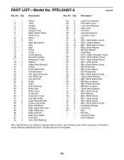
... change without notice. PART LIST-Model No. Grease Packet * - Qty. Description 1 1 Frame 2 1 Track 3 1 Upright 4 1 Console 5 1 Upright Cover 6 1 Water Bottle Holder 7 1 Track Cover 8 2 Wheel 9 3 Foot 10 1 Eddy Mechanism 11 1 Axle 12 1 Idler 13 1 Pulley 14 1 Crank 15 2 Crank Bearing 16 1 Resistance Motor 17 1 Resistance Cable 18 2 Magnet 19 2 Upper Body Bushing 20 1 Clamp 21 1 Reed Switch/Wire 22 1 Left Handlebar 23 1 Left Upper Body Arm 24 1 Left Pedal Leg 25 1 Left Link Arm 26 2 Pedal 27 2 Roller...
... change without notice. PART LIST-Model No. Grease Packet * - Qty. Description 1 1 Frame 2 1 Track 3 1 Upright 4 1 Console 5 1 Upright Cover 6 1 Water Bottle Holder 7 1 Track Cover 8 2 Wheel 9 3 Foot 10 1 Eddy Mechanism 11 1 Axle 12 1 Idler 13 1 Pulley 14 1 Crank 15 2 Crank Bearing 16 1 Resistance Motor 17 1 Resistance Cable 18 2 Magnet 19 2 Upper Body Bushing 20 1 Clamp 21 1 Reed Switch/Wire 22 1 Left Handlebar 23 1 Left Upper Body Arm 24 1 Left Pedal Leg 25 1 Left Link Arm 26 2 Pedal 27 2 Roller...
English Manual
Page 24
... to the original purchaser. To help us : • the model number and serial number of the product (see the front cover of this manual) • the name of the product (see the front cover of this manual) • the key number and description of the replacement part(s) (see the front cover of merchantability or fitness for a particular purpose is authorized by an ICON authorized service center;
... to the original purchaser. To help us : • the model number and serial number of the product (see the front cover of this manual) • the name of the product (see the front cover of this manual) • the key number and description of the replacement part(s) (see the front cover of merchantability or fitness for a particular purpose is authorized by an ICON authorized service center;

