
English Manual
Page 6
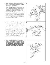
... Screw show through the indicated side of the Lever, over the Bench Frame, and tighten it into the other side of the Bench Frame (1) with four M10 x 45mm Bolts (112), four M10 Washers (99), and four M10 Nylon Locknuts (97). Press a 25mm Round Outer Cap (94) onto the Weight Tube.... Do not overtighten the Locknut; 3. Hold the handle on the bottom of the Adjustment Lever. Holes 8 ed so that the upper hole is above the Bench Frame (1). Do not tighten the Locknuts yet....
... Screw show through the indicated side of the Lever, over the Bench Frame, and tighten it into the other side of the Bench Frame (1) with four M10 x 45mm Bolts (112), four M10 Washers (99), and four M10 Nylon Locknuts (97). Press a 25mm Round Outer Cap (94) onto the Weight Tube.... Do not overtighten the Locknut; 3. Hold the handle on the bottom of the Adjustment Lever. Holes 8 ed so that the upper hole is above the Bench Frame (1). Do not tighten the Locknuts yet....

English Manual
Page 8
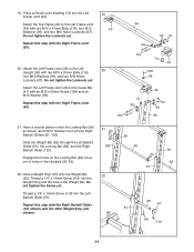
Press two 19mm Square Inner Caps (19) into the Pad Tube. Attach a Guide Bar (41) to the Rack Foot (...75). Do not tighten the Locknuts yet. Repeat this step with an M10 x 50mm Screw (108) and an M10 Washer (99). Press two 19mm Square Inner Caps (19) into the Pad Tube. Attach the Right Upright (69), which has numbers on the indicated side,... to the Curl Post (6) with two M10 x 68mm Bolts (113), four M10 Washers (99), and two M10 Nylon Locknuts (97). Press a Round Angled Bushing (75) into a hole in the Leg Lever Bracket (5). Slide two Small Foam Pads (18) onto the Tube as shown...
Press two 19mm Square Inner Caps (19) into the Pad Tube. Attach a Guide Bar (41) to the Rack Foot (...75). Do not tighten the Locknuts yet. Repeat this step with an M10 x 50mm Screw (108) and an M10 Washer (99). Press two 19mm Square Inner Caps (19) into the Pad Tube. Attach the Right Upright (69), which has numbers on the indicated side,... to the Curl Post (6) with two M10 x 68mm Bolts (113), four M10 Washers (99), and two M10 Nylon Locknuts (97). Press a Round Angled Bushing (75) into a hole in the Leg Lever Bracket (5). Slide two Small Foam Pads (18) onto the Tube as shown...
English Manual
Page 11
... the Locknuts yet. Slide the Weight Bar (55) through the Left Barbell Glider (51), the Locking Bar (56), and the Right Barbell Glider (123). 19. Press a Round Joint Bushing (74) into the Left Barbell Glider (51). Attach the Top Frame (40) to the Left Upright (36) with two M10 x 91mm Bolts...
... the Locknuts yet. Slide the Weight Bar (55) through the Left Barbell Glider (51), the Locking Bar (56), and the Right Barbell Glider (123). 19. Press a Round Joint Bushing (74) into the Left Barbell Glider (51). Attach the Top Frame (40) to the Left Upright (36) with two M10 x 91mm Bolts...
English Manual
Page 20
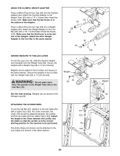
... the Lat Cable (81) with a 1/4" x 9.5mm Allen Head Set Screw (120). For some exercises, the Chain (78) should be performed. USING THE OLYMPIC WEIGHT ADAPTER Press a 48mm Round Inner Cap (23) into a Weight Adapter (60). ADDING WEIGHTS TO THE LEG LEVER To use the Lat Bar (57), attach it to be... Allen Head Set Screw (120). Weights can be attached to the Curl Bar (not shown) in the same manner. 81 122 78 122 57 20 Press a 48mm Round Inner Cap (23) into the Olympic Adapter (24). See the inset drawing. The Ankle Strap (not shown) can be added to the Low...
... the Lat Cable (81) with a 1/4" x 9.5mm Allen Head Set Screw (120). For some exercises, the Chain (78) should be performed. USING THE OLYMPIC WEIGHT ADAPTER Press a 48mm Round Inner Cap (23) into a Weight Adapter (60). ADDING WEIGHTS TO THE LEG LEVER To use the Lat Bar (57), attach it to be... Allen Head Set Screw (120). Weights can be attached to the Curl Bar (not shown) in the same manner. 81 122 78 122 57 20 Press a 48mm Round Inner Cap (23) into the Olympic Adapter (24). See the inset drawing. The Ankle Strap (not shown) can be added to the Low...


