

English Manual
Page 1
... all precautions and instructions in the space above for future reference. As a manufacturer, we are missing or damaged parts, we will provide immediate assistance, free of charge. The trained technicians on our customer hot line will guarantee complete satisfaction through direct assistance from our factory. PFB48031 Serial No. Write the serial number in this manual before using this manual for future reference...
... all precautions and instructions in the space above for future reference. As a manufacturer, we are missing or damaged parts, we will provide immediate assistance, free of charge. The trained technicians on our customer hot line will guarantee complete satisfaction through direct assistance from our factory. PFB48031 Serial No. Write the serial number in this manual before using this manual for future reference...
English Manual
Page 2
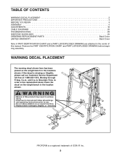
... PLACEMENT 2 IMPORTANT PRECAUTIONS 3 BEFORE YOU BEGIN 4 ASSEMBLY 5 ADJUSTMENTS 19 CABLE DIAGRAMS 22 TROUBLESHOOTING 23 EXERCISE GUIDELINES 24 ORDERING REPLACEMENT PARTS Back Cover LIMITED WARRANTY Back Cover Note: A PART IDENTIFICATION CHART and a PART LIST/EXPLODED DRAWING are attached in the center of ICON IP, Inc. 2 until 6 p.m. Remove the PART IDENTIFICATION CHART and PART LIST/EXPLODED DRAWING before beginning assembly. PROFORM is missing or illegible, please call our Customer Service Department toll-free at 1-888-533-1333, Monday through...
... PLACEMENT 2 IMPORTANT PRECAUTIONS 3 BEFORE YOU BEGIN 4 ASSEMBLY 5 ADJUSTMENTS 19 CABLE DIAGRAMS 22 TROUBLESHOOTING 23 EXERCISE GUIDELINES 24 ORDERING REPLACEMENT PARTS Back Cover LIMITED WARRANTY Back Cover Note: A PART IDENTIFICATION CHART and a PART LIST/EXPLODED DRAWING are attached in the center of ICON IP, Inc. 2 until 6 p.m. Remove the PART IDENTIFICATION CHART and PART LIST/EXPLODED DRAWING before beginning assembly. PROFORM is missing or illegible, please call our Customer Service Department toll-free at 1-888-533-1333, Monday through...
English Manual
Page 3
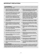
.... If the cables bind as described in this product. 3 ICON assumes no responsibility for persons over the age of 35 or persons with pre-existing health problems. Read all parts are used . Always place an equal amount of weight on the barbell guides or safety spotters. Make sure all instructions before using the weight bench. 1. Always set screws attaching the Olympic weight adapters are properly tightened each time...
.... If the cables bind as described in this product. 3 ICON assumes no responsibility for persons over the age of 35 or persons with pre-existing health problems. Read all parts are used . Always place an equal amount of weight on the barbell guides or safety spotters. Make sure all instructions before using the weight bench. 1. Always set screws attaching the Olympic weight adapters are properly tightened each time...
English Manual
Page 4
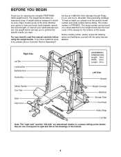
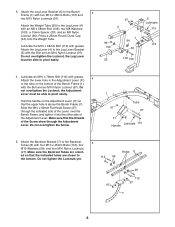
... parts that are determined relative to a person sitting on a decal attached to the weight bench (see the front cover of this manual carefully before calling. The model number is to right and left side" are labeled. Right Side Lat Bar Locking Bar Butterfly Arm Guide Bar ASSEMBLED DIMENSIONS: Height: 75 in . Left Side Barbell Safety Spotter Curl Pad Seat Leg Lever Weight Carriage Backrest Storage Tube Foot Plate Ankle Strap Curl Bar...
... parts that are determined relative to a person sitting on a decal attached to the weight bench (see the front cover of this manual carefully before calling. The model number is to right and left side" are labeled. Right Side Lat Bar Locking Bar Butterfly Arm Guide Bar ASSEMBLED DIMENSIONS: Height: 75 in . Left Side Barbell Safety Spotter Curl Pad Seat Leg Lever Weight Carriage Backrest Storage Tube Foot Plate Ankle Strap Curl Bar...
English Manual
Page 5
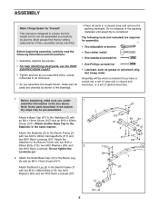
... weight bench can be assembled successfully by setting aside plenty of ratchet wrenches. 1. Before beginning, make sure you assemble the weight bench, make sure all parts are required for Yourself This manual is completed. ASSEMBLY Make Things Easier for assembly: • Two adjustable wrenches • One rubber mallet • One standard screwdriver • One Phillips screwdriver • Lubricant, such as you assemble them, unless instructed...
... weight bench can be assembled successfully by setting aside plenty of ratchet wrenches. 1. Before beginning, make sure you assemble the weight bench, make sure all parts are required for Yourself This manual is completed. ASSEMBLY Make Things Easier for assembly: • Two adjustable wrenches • One rubber mallet • One standard screwdriver • One Phillips screwdriver • Lubricant, such as you assemble them, unless instructed...
English Manual
Page 6
... of the Screw show through the indicated side of the Lever, over the Bench Frame, and tighten it into the other side of the Bench Frame (1) with the Bolt and an M10 Nylon Locknut (97). Attach the lower hole in the Adjustment Lever (11) 4 to the bottom. Attach the Leg Lever Bracket (5) to the Leg Lever Bracket (5) with the Bolt and an...
... of the Screw show through the indicated side of the Lever, over the Bench Frame, and tighten it into the other side of the Bench Frame (1) with the Bolt and an M10 Nylon Locknut (97). Attach the lower hole in the Adjustment Lever (11) 4 to the bottom. Attach the Leg Lever Bracket (5) to the Leg Lever Bracket (5) with the Bolt and an...

English Manual
Page 7
Lubricate an M10 x 155mm Bolt (109) with four M6 x 38mm Screws (102) and four M6 Washers (101). Attach the Backrest (14) to the Bench Frame (1) with the Bolt, two M10 Washers (99), and an M10 Nylon Locknut (97). Attach the Seat (15) to the Backrest Tubes (8) with grease. Attach the ... 62mm Flat Head Screw (27) is under the Adjustment Lever (11). Tighten the six M10 Nylon Locknuts (97) used in the Backrest Bracket. Insert the Backrest Bracket (7) through the slot in the Bench Frame (1) and under a notch in steps 1 and 5. 6 97 99 8 27 1 7 11 7 99 109 Lubricate 14 8 8.
Lubricate an M10 x 155mm Bolt (109) with four M6 x 38mm Screws (102) and four M6 Washers (101). Attach the Backrest (14) to the Bench Frame (1) with the Bolt, two M10 Washers (99), and an M10 Nylon Locknut (97). Attach the Seat (15) to the Backrest Tubes (8) with grease. Attach the ... 62mm Flat Head Screw (27) is under the Adjustment Lever (11). Tighten the six M10 Nylon Locknuts (97) used in the Backrest Bracket. Insert the Backrest Bracket (7) through the slot in the Bench Frame (1) and under a notch in steps 1 and 5. 6 97 99 8 27 1 7 11 7 99 109 Lubricate 14 8 8.

English Manual
Page 10
...not tighten the Locknuts yet. 15. Attach the Right Base (34) to the Right Base (34) with three M10 x 68mm Bolts (113), three M10 Washers (99), and two M10 Nylon Locknuts (97). Identify the Left and Right Barbell Gliders (51, 123) by the position of the Right Upright (69). Always set both... 51 Screw Hole 41 41 69 36 10 Attach the Right Spotter Hook (53) to the indicated Upright (36, 69). Slide each Barbell Glider (51, 123) onto the Guide Bar (41) next to a Safety Spotter (52) with two M10 x 68mm Bolts (113), four M10 Washers (99), and two M10 Nylon Locknuts (97). Using a ...
...not tighten the Locknuts yet. 15. Attach the Right Base (34) to the Right Base (34) with three M10 x 68mm Bolts (113), three M10 Washers (99), and two M10 Nylon Locknuts (97). Identify the Left and Right Barbell Gliders (51, 123) by the position of the Right Upright (69). Always set both... 51 Screw Hole 41 41 69 36 10 Attach the Right Spotter Hook (53) to the indicated Upright (36, 69). Slide each Barbell Glider (51, 123) onto the Guide Bar (41) next to a Safety Spotter (52) with two M10 x 68mm Bolts (113), four M10 Washers (99), and two M10 Nylon Locknuts (97). Using a ...

English Manual
Page 12
...Nylon Locknut (97). Slide the Barbell Adapter (59) onto the Weight 23 Bar (55). Attach a Weight Carriage Stop to the Center Base (32) with the hexagonal holes on top. Do not tighten the Locknut yet. Attach the Rear Upright (38), with an M10 x 75mm Bolt (127), two M10 Washers (99...Allen Head Set Screw (120) into the Barbell Adapter. 23. Do not tighten the Locknut yet. Repeat this step with two M10 x 75mm Bolts (127), four M10 Washers (99), and two M10 Nylon Locknuts (97). Attach the Center Upright (37) to the Rear Base (33) with the other Barbell Adapter (not ...
...Nylon Locknut (97). Slide the Barbell Adapter (59) onto the Weight 23 Bar (55). Attach a Weight Carriage Stop to the Center Base (32) with the hexagonal holes on top. Do not tighten the Locknut yet. Attach the Rear Upright (38), with an M10 x 75mm Bolt (127), two M10 Washers (99...Allen Head Set Screw (120) into the Barbell Adapter. 23. Do not tighten the Locknut yet. Repeat this step with two M10 x 75mm Bolts (127), four M10 Washers (99), and two M10 Nylon Locknuts (97). Attach the Center Upright (37) to the Rear Base (33) with the other Barbell Adapter (not ...

English Manual
Page 14
...Arm. Attach the Left Fly Arm (44) in step 23. 110 99 99 39 37 97 97 42 29. Attach the Butterfly Frame (42) to the Rear Top 28 Frame (39) with the included retainer tool. Note: Be careful not to the Left Fly Arm (44) with two M10 x 68mm Bolts... slide the Foam Pad onto the Arm. Do not tighten the Locknuts yet. Attach the Butterfly Frame (42) to verify cable routing. Tighten the 1/4" x 14mm Screws (119) used in step 22 and the 1/4" x 9.5mm Allen Head Set Screws (120) used in the inset drawing. During cable assembly, refer to the CABLE DIAGRAMS on the Butterfly Frame. 28. ...
...Arm. Attach the Left Fly Arm (44) in step 23. 110 99 99 39 37 97 97 42 29. Attach the Butterfly Frame (42) to the Rear Top 28 Frame (39) with the included retainer tool. Note: Be careful not to the Left Fly Arm (44) with two M10 x 68mm Bolts... slide the Foam Pad onto the Arm. Do not tighten the Locknuts yet. Attach the Butterfly Frame (42) to verify cable routing. Tighten the 1/4" x 14mm Screws (119) used in step 22 and the 1/4" x 9.5mm Allen Head Set Screws (120) used in the inset drawing. During cable assembly, refer to the CABLE DIAGRAMS on the Butterfly Frame. 28. ...
English Manual
Page 18
... all parts have been properly tightened. See TROUBLESHOOTING on page 22 of the cables does not move smoothly over the pulleys. 44. Attach the Low Cable (82) inside the Rear Base 44 (33) with two M6 x 72mm Screws (105) and two M6 Washers (101). 80 37 105 101 101 105 46. Do not overtighten the Locknut; Before using the weight bench, pull each cable...
... all parts have been properly tightened. See TROUBLESHOOTING on page 22 of the cables does not move smoothly over the pulleys. 44. Attach the Low Cable (82) inside the Rear Base 44 (33) with two M6 x 72mm Screws (105) and two M6 Washers (101). 80 37 105 101 101 105 46. Do not overtighten the Locknut; Before using the weight bench, pull each cable...

English Manual
Page 19
... the Leg Lever Bracket. Replace any worn parts immediately. The weight bench can be stored on the tube on page 24 for each time the weight bench is fully engaged before disengaging the Backrest Bracket (7). Tighten the Curl Knob (29) into the Leg Lever Bracket (5). Fully tighten the Knob. Do not use solvents. Lower the Adjust- Make sure all parts are properly tightened each exercise. See the EXERCISE GUIDELINES...
... the Leg Lever Bracket. Replace any worn parts immediately. The weight bench can be stored on the tube on page 24 for each time the weight bench is fully engaged before disengaging the Backrest Bracket (7). Tighten the Curl Knob (29) into the Leg Lever Bracket (5). Fully tighten the Knob. Do not use solvents. Lower the Adjust- Make sure all parts are properly tightened each exercise. See the EXERCISE GUIDELINES...
English Manual
Page 20
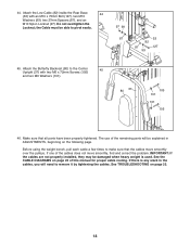
... WEIGHT ADAPTER Press a 48mm Round Inner Cap (23) into a Weight Adapter (60). ADDING WEIGHTS TO THE LEG LEVER To use the Lat Bar (57), attach it to the Low Cable (not shown) in the same manner. Weights can be stored on the Weight Tube (25) or the Curl Bar. (76). The Ankle Strap (not shown) can be attached to the Lat Cable (81) with a 1/4" x 9.5mm Allen Head Set Screw (120). Attach the Weight Adapter...
... WEIGHT ADAPTER Press a 48mm Round Inner Cap (23) into a Weight Adapter (60). ADDING WEIGHTS TO THE LEG LEVER To use the Lat Bar (57), attach it to the Low Cable (not shown) in the same manner. Weights can be stored on the Weight Tube (25) or the Curl Bar. (76). The Ankle Strap (not shown) can be attached to the Lat Cable (81) with a 1/4" x 9.5mm Allen Head Set Screw (120). Attach the Weight Adapter...

English Manual
Page 21
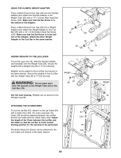
...: Always set both hands. WARNING: Do not place more than 310 pounds on the barbell or 150 pounds on each side of weight (not included) onto the Barbell Adapters (59) or Weight Carriage. Turn the Locking Bar until the hooks engage the slots in the Uprights (36 [not shown], 69). Raise or lower the Safety Spotters to move the...
...: Always set both hands. WARNING: Do not place more than 310 pounds on the barbell or 150 pounds on each side of weight (not included) onto the Barbell Adapters (59) or Weight Carriage. Turn the Locking Bar until the hooks engage the slots in the Uprights (36 [not shown], 69). Raise or lower the Safety Spotters to move the...
English Manual
Page 23
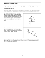
... a cable slips off the pulleys repeatedly, it . Slack can be removed from the cables in the groove of the Pulley Plates with the Bolt and Locknut. To do this manual. 23 Remove the cable and re-install it may have become twisted. Reattach the Pulley and the Cable Trap between a set of holes closer to be replaced, see ORDERING REPLACEMENT PARTS on the weight bench, can be tightened. To tighten the cables, remove...
... a cable slips off the pulleys repeatedly, it . Slack can be removed from the cables in the groove of the Pulley Plates with the Bolt and Locknut. To do this manual. 23 Remove the cable and re-install it may have become twisted. Reattach the Pulley and the Cable Trap between a set of holes closer to be replaced, see ORDERING REPLACEMENT PARTS on the weight bench, can be tightened. To tighten the cables, remove...
English Manual
Page 24
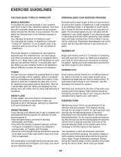
...-balanced fitness program. Refer to the muscle chart on Monday, Wednesday, and Friday. • Plan 20 to 30 minutes of aerobic exercise, such as one day of an individual exercise in each set . Select a moderate amount of resistance and increase the number of repetitions in two ways: • by changing the amount of resistance used • by increasing circulation, raising your body...
...-balanced fitness program. Refer to the muscle chart on Monday, Wednesday, and Friday. • Plan 20 to 30 minutes of aerobic exercise, such as one day of an individual exercise in each set . Select a moderate amount of resistance and increase the number of repetitions in two ways: • by changing the amount of resistance used • by increasing circulation, raising your body...
English Manual
Page 25
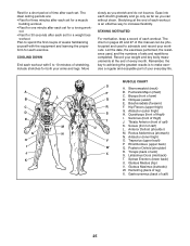
... the proper form for each exercise. Abductor (outer thigh) H. Soleus (front of leg) X. Trapezius (upper back) P. Rhomboideus (upper back) Q. Latissimus Dorsi (mid back) T. out. • Rest for 30 seconds after each set for a toning work- Record your weight and key body measurements at the end of each workout is to make exercise a regular and enjoyable part of your arms and legs. Gluteus Medius...
... the proper form for each exercise. Abductor (outer thigh) H. Soleus (front of leg) X. Trapezius (upper back) P. Rhomboideus (upper back) Q. Latissimus Dorsi (mid back) T. out. • Rest for 30 seconds after each set for a toning work- Record your weight and key body measurements at the end of each workout is to make exercise a regular and enjoyable part of your arms and legs. Gluteus Medius...

English Manual
Page 28
... parentheses by each drawing is not in the parts bag, check to identify small parts used in the center of this manual. PFB48031 R1204A Refer to the drawings below to see if it has been pre-attached. If a part is the key number of the part, from the PART LIST in assembly. PART IDENTIFICATION CHART-Model No. M10 Nylon Locknut (97) M8 Nylon Locknut (96...
... parentheses by each drawing is not in the parts bag, check to identify small parts used in the center of this manual. PFB48031 R1204A Refer to the drawings below to see if it has been pre-attached. If a part is the key number of the part, from the PART LIST in assembly. PART IDENTIFICATION CHART-Model No. M10 Nylon Locknut (97) M8 Nylon Locknut (96...
English Manual
Page 30
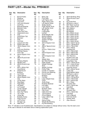
... Screw 1/4" x 14mm Screw 1/4" x 9.5mm Allen Head Set Screw M10 x 25mm Screw Cable Clip Right Barbell Glider M6 Nylon Locknut Small Cable Trap M10 x 127mm Bolt M10 x 75mm Bolt M10 x 60mm Bolt M8 x 16mm Shoulder Bolt M10 x 72mm Hex Head Bolt M8 x 12mm Shoulder Bolt M10 x 19mm Hex Head Bolt User's Manual Exercise Guide Grease Pack Allen Wrench Note: "#" indicates a non-illustrated part. Key Qty. Specifications are subject to change without notice. PFB48031 R1204A Key...
... Screw 1/4" x 14mm Screw 1/4" x 9.5mm Allen Head Set Screw M10 x 25mm Screw Cable Clip Right Barbell Glider M6 Nylon Locknut Small Cable Trap M10 x 127mm Bolt M10 x 75mm Bolt M10 x 60mm Bolt M8 x 16mm Shoulder Bolt M10 x 72mm Hex Head Bolt M8 x 12mm Shoulder Bolt M10 x 19mm Hex Head Bolt User's Manual Exercise Guide Grease Pack Allen Wrench Note: "#" indicates a non-illustrated part. Key Qty. Specifications are subject to change without notice. PFB48031 R1204A Key...
English Manual
Page 33
... which vary from the date of purchase. Mountain Time (excluding holidays). ORDERING REPLACEMENT PARTS To order replacement parts, simply call our Customer Service Department toll-free at the center of this manual) LIMITED WARRANTY ICON Health & Fitness, Inc. (ICON), warrants this product to be free from defects in workmanship and material, under this manual) 4. The MODEL NUMBER of the product (PROFORM C900 weight bench) 3. No other consequential damages of whatsoever nature.
... which vary from the date of purchase. Mountain Time (excluding holidays). ORDERING REPLACEMENT PARTS To order replacement parts, simply call our Customer Service Department toll-free at the center of this manual) LIMITED WARRANTY ICON Health & Fitness, Inc. (ICON), warrants this product to be free from defects in workmanship and material, under this manual) 4. The MODEL NUMBER of the product (PROFORM C900 weight bench) 3. No other consequential damages of whatsoever nature.

