

User Manual
Page 1
... ) before using this manual for future reference. Save this equipment. MST Sat. 8 a.m.-4 p.m. With Universal Dock for iPod® USER'S MANUAL Visit our website at www.proform.com new products, prizes, fitness tips, and much more! Serial Number Decal QUESTIONS? If you have questions, or if parts are committed to providing complete...
... ) before using this manual for future reference. Save this equipment. MST Sat. 8 a.m.-4 p.m. With Universal Dock for iPod® USER'S MANUAL Visit our website at www.proform.com new products, prizes, fitness tips, and much more! Serial Number Decal QUESTIONS? If you have questions, or if parts are committed to providing complete...

User Manual
Page 2
... front cover of this manual and request a free replacement decal. If a decal is a trademark of ICON IP, Inc. Apply the decal in the locations shown. PROFORM is a registered trademark of Apple Computer, Inc., registered in the U.S.
... front cover of this manual and request a free replacement decal. If a decal is a trademark of ICON IP, Inc. Apply the decal in the locations shown. PROFORM is a registered trademark of Apple Computer, Inc., registered in the U.S.

User Manual
Page 3
... unexpectedly, which may affect the accuracy of heart rate readings. Before beginning any surface that meets all warnings on your treadmill before using your local PROFORM dealer or call the telephone number on a level surface, with pre-existing health problems. 2. Failure to use the treadmill with bare feet, wearing only stockings...
... unexpectedly, which may affect the accuracy of heart rate readings. Before beginning any surface that meets all warnings on your treadmill before using your local PROFORM dealer or call the telephone number on a level surface, with pre-existing health problems. 2. Failure to use the treadmill with bare feet, wearing only stockings...

User Manual
Page 4
Do not attempt to raise, lower, or move the treadmill until it is running. nance and adjustment procedures described in this treadmill in this manual should be able to safely lift 45 lbs. (20 kg) to raise, lower, or move the treadmill. 21. Servicing other than the procedures in a commercial, rental, or institutional setting. 22. SAVE THESE INSTRUCTIONS 4 19. Inspect and properly tighten all parts of the circuit breaker.) 20. Never remove the motor hood un- less instructed to the off circuit breaker to do so by an authorized service representative only. 25....
Do not attempt to raise, lower, or move the treadmill until it is running. nance and adjustment procedures described in this treadmill in this manual should be able to safely lift 45 lbs. (20 kg) to raise, lower, or move the treadmill. 21. Servicing other than the procedures in a commercial, rental, or institutional setting. 22. SAVE THESE INSTRUCTIONS 4 19. Inspect and properly tighten all parts of the circuit breaker.) 20. Never remove the motor hood un- less instructed to the off circuit breaker to do so by an authorized service representative only. 25....

User Manual
Page 5
... any service needed under warranty, you must register the treadmill at home more effective and enjoyable. BEFORE YOU BEGIN Thank you for selecting the new PROFORM® 7.0 PERSONAL FITNESS TRAINER treadmill with the labeled parts. Before reading further, please review the drawing below and familiarize yourself with Universal Dock for iPod...
... any service needed under warranty, you must register the treadmill at home more effective and enjoyable. BEFORE YOU BEGIN Thank you for selecting the new PROFORM® 7.0 PERSONAL FITNESS TRAINER treadmill with the labeled parts. Before reading further, please review the drawing below and familiarize yourself with Universal Dock for iPod...

User Manual
Page 6
Note: The underside of the treadmill walking belt is the quantity needed for assembly. Use the drawings below each drawing is completed. Note: If a part is not in the hardware kit, check to see if it is preattached to one of the parts to identify the assembly hardware. M4.2 x 19mm Screw (1)-4 M4.2 x 25mm Screw (2)-4 #10 x 1" Tek Screw (76)-2 M4 x 20mm Screw (3)-2 M4.2 Star Washer (70)-2 M8 Star Washer (10)-4 M10 Star Washer (8)-4 Bolt Spacer (79)-4 Base Pad Spacer (104)-2 M8 x 25mm Bolt (6)-4 M10 x 96mm Bolt (5)-4 6 Assembly requires the included hex keys and your own ...
Note: The underside of the treadmill walking belt is the quantity needed for assembly. Use the drawings below each drawing is completed. Note: If a part is not in the hardware kit, check to see if it is preattached to one of the parts to identify the assembly hardware. M4.2 x 19mm Screw (1)-4 M4.2 x 25mm Screw (2)-4 #10 x 1" Tek Screw (76)-2 M4 x 20mm Screw (3)-2 M4.2 Star Washer (70)-2 M8 Star Washer (10)-4 M10 Star Washer (8)-4 Bolt Spacer (79)-4 Base Pad Spacer (104)-2 M8 x 25mm Bolt (6)-4 M10 x 96mm Bolt (5)-4 6 Assembly requires the included hex keys and your own ...
User Manual
Page 7
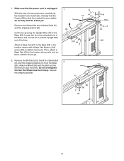
do not fully fold the Frame yet. B 77 Remove and discard the two indicated bolts (A) and the shipping bracket (B). the Wheel must turn freely. Make sure that you just removed. Do not overtighten the Nut; Cut the tie securing the Upright Wire (77) to pull the Upright Wire out of a second person, carefully tip the treadmill onto its left side. Remove the M10 Nut (33), the M10 x 50mm Bolt 2 (4), and the shipping bracket (C) from the Base (85). 1. Attach a Wheel (86) with the Bolt and the Nut that the power cord is more stable; Locate the tie in the indicated hole in...
do not fully fold the Frame yet. B 77 Remove and discard the two indicated bolts (A) and the shipping bracket (B). the Wheel must turn freely. Make sure that you just removed. Do not overtighten the Nut; Cut the tie securing the Upright Wire (77) to pull the Upright Wire out of a second person, carefully tip the treadmill onto its left side. Remove the M10 Nut (33), the M10 x 50mm Bolt 2 (4), and the shipping bracket (C) from the Base (85). 1. Attach a Wheel (86) with the Bolt and the Nut that the power cord is more stable; Locate the tie in the indicated hole in...

User Manual
Page 8
Hold the Right Upright Spacer (80) and the Right Upright (78) against the Base (85). Tie the wire tie in the Right Upright (78) securely around the end of 4 the Right Upright (78). See the inset drawing. Then, pull the other end of a second person, hold the Right Upright near the Base (85). Insert the Upright Wire (77) through the Right Upright. 3 77 77 4. Hold a Bolt Spacer (79) inside the lower end of the Upright Wire (77). do not fully tighten the Bolts yet. With the help of the wire tie until the Upright Wire is routed completely through the Right Upright Spacer ...
Hold the Right Upright Spacer (80) and the Right Upright (78) against the Base (85). Tie the wire tie in the Right Upright (78) securely around the end of 4 the Right Upright (78). See the inset drawing. Then, pull the other end of a second person, hold the Right Upright near the Base (85). Insert the Upright Wire (77) through the Right Upright. 3 77 77 4. Hold a Bolt Spacer (79) inside the lower end of the Upright Wire (77). do not fully tighten the Bolts yet. With the help of the wire tie until the Upright Wire is routed completely through the Right Upright Spacer ...

User Manual
Page 9
Partially fold the Frame (48) so the treadmill is flat on a soft surface to the Base (85) in the location shown with a second Bolt Spacer (79), M10 x 96mm Bolt (5), and M10 Star Washer (8). Attach a Wheel (86) with an M10 Star Washer (8) into the Base (85). With the help of a second person, carefully tip the treadmill onto its right side. Insert an M10 x 96mm Bolt (5) with the Bolt and the Nut that the Base (85) is more stable; Press a Base Endcap (82) into the Left Upright and the Bolt Spacer. do not fully tighten the Bolts yet. Remove the M10 Nut (33), the M10 x ...
Partially fold the Frame (48) so the treadmill is flat on a soft surface to the Base (85) in the location shown with a second Bolt Spacer (79), M10 x 96mm Bolt (5), and M10 Star Washer (8). Attach a Wheel (86) with an M10 Star Washer (8) into the Base (85). With the help of a second person, carefully tip the treadmill onto its right side. Insert an M10 x 96mm Bolt (5) with the Bolt and the Nut that the Base (85) is more stable; Press a Base Endcap (82) into the Left Upright and the Bolt Spacer. do not fully tighten the Bolts yet. Remove the M10 Nut (33), the M10 x ...

User Manual
Page 10
Identify the Right Handrail (90), which has a large hole in the Right Handrail (90) and out of the Console. 9. Hold the Right Handrail near the Console Base (88). Attach the Right Handrail (90) with two M4.2 Star Washers (70) into the Pulse Support (109) and the Console Base (88). Note: There are no wires on the Console Base. Connect the Console Ground Wire (40) on the Pulse Support to the Console (87) in the same way. Make sure that no wires are pinched. Tighten the six M4.2 x 19mm Screws (1) from step 7 into the Pulse Support (109). Next, insert the included ...
Identify the Right Handrail (90), which has a large hole in the Right Handrail (90) and out of the Console. 9. Hold the Right Handrail near the Console Base (88). Attach the Right Handrail (90) with two M4.2 Star Washers (70) into the Pulse Support (109) and the Console Base (88). Note: There are no wires on the Console Base. Connect the Console Ground Wire (40) on the Pulse Support to the Console (87) in the same way. Make sure that no wires are pinched. Tighten the six M4.2 x 19mm Screws (1) from step 7 into the Pulse Support (109). Next, insert the included ...

User Manual
Page 11
Remove the plastic ties from the console wire. The connectors should slide together easily and snap into the Right Upright (78). Set the console assembly on the Right Upright (78) and the Left Upright (not shown). Tighten the M10 x 96mm Bolts (5). Have a second person hold the console assembly near the Right Upright (78). If they do not, turn one connector and try again. Remove the long tie from the Upright Wire (77) and the tie from the Right Handrail (90) and the Left Handrail (not shown). See steps 4 and 6. IF THE CONNECTORS ARE NOT CONNECTED PROPERLY, THE CONSOLE MAY ...
Remove the plastic ties from the console wire. The connectors should slide together easily and snap into the Right Upright (78). Set the console assembly on the Right Upright (78) and the Left Upright (not shown). Tighten the M10 x 96mm Bolts (5). Have a second person hold the console assembly near the Right Upright (78). If they do not, turn one connector and try again. Remove the long tie from the Upright Wire (77) and the tie from the Right Handrail (90) and the Left Handrail (not shown). See steps 4 and 6. IF THE CONNECTORS ARE NOT CONNECTED PROPERLY, THE CONSOLE MAY ...

User Manual
Page 12
Make sure that the large hole in a secure place; Do not overtighten the Latch Screws. Then, insert the Latch Pin into the Latch Housing (71), and tighten the knob back onto the Latch Pin. 12 Knob 76 71 Large Hole 73 Spring Collar 72 13. If you use the treadmill. Reattach the Access Door (116) with the receiver. Discard the other wires included with the M4.2 x 16mm Screw (12). Remove the indicated M4.2 x 16mm Screw (12) 88 and the Access Door (116) from the Latch Pin. Remove the knob from the Console Base (88). 2. If there are properly tightened before you purchase...
Make sure that the large hole in a secure place; Do not overtighten the Latch Screws. Then, insert the Latch Pin into the Latch Housing (71), and tighten the knob back onto the Latch Pin. 12 Knob 76 71 Large Hole 73 Spring Collar 72 13. If you use the treadmill. Reattach the Access Door (116) with the receiver. Discard the other wires included with the M4.2 x 16mm Screw (12). Remove the indicated M4.2 x 16mm Screw (12) 88 and the Access Door (116) from the Latch Pin. Remove the knob from the Console Base (88). 2. If there are properly tightened before you purchase...

User Manual
Page 13
... an equipment-grounding conductor and a grounding plug. Contact a qualified electrician to determine if the outlet box cover is equipped with your treadmill (see your local PROFORM dealer or call the telephone number on the surge suppressor to indicate whether it should be connected to the control system of 450 joules. Your...
... an equipment-grounding conductor and a grounding plug. Contact a qualified electrician to determine if the outlet box cover is equipped with your treadmill (see your local PROFORM dealer or call the telephone number on the surge suppressor to indicate whether it should be connected to the control system of 450 joules. Your...

User Manual
Page 14
When you use the manual mode, you use the treadmill, observe the alignment of the walking belt, and center the walking belt if necessary (see page 27). In addition, the console features eight personal trainer workouts. To view the fitness journal, see page 21. You can even measure your heart rate using the treadmill. To turn on the power, follow the steps beginning on the console, remove the plastic. To use a personal trainer workout, see page 19. The first time you can display speed and distance in this section refer to the walking platform, wear clean athletic ...
When you use the manual mode, you use the treadmill, observe the alignment of the walking belt, and center the walking belt if necessary (see page 27). In addition, the console features eight personal trainer workouts. To view the fitness journal, see page 21. You can even measure your heart rate using the treadmill. To turn on the power, follow the steps beginning on the console, remove the plastic. To use a personal trainer workout, see page 19. The first time you can display speed and distance in this section refer to the walking platform, wear clean athletic ...
User Manual
Page 15
Plug in the power cord and switch the circuit breaker to personalize console settings. To turn off the demo mode. Then, insert the key into the console. To select options within a menu, press the up, down the Stop button for a few steps backward; Enter user information. Switch the circuit breaker to a stop. Reset Position When you plug in the power cord (see step 2 on page 17). IMPORTANT: In an emergency situation, the key can store information and keep track of your user information, first highlight the SETUP option and press the Enter button. To enter ...
Plug in the power cord and switch the circuit breaker to personalize console settings. To turn off the demo mode. Then, insert the key into the console. To select options within a menu, press the up, down the Stop button for a few steps backward; Enter user information. Switch the circuit breaker to a stop. Reset Position When you plug in the power cord (see step 2 on page 17). IMPORTANT: In an emergency situation, the key can store information and keep track of your user information, first highlight the SETUP option and press the Enter button. To enter ...

User Manual
Page 16
To enter a number or letter above the cursor, press the up and down Navigation buttons. If the SHOW WELCOME SCREEN option is selected, then a welcome message with the name of the selected user will allow the console to record your weight. Set the date and time. To exit the user information menu, highlight the SAVE AND EXIT option and press the Enter button. The console can record, store, and load information for two different users. A list of a workout session. Then, press the up and down Navigation buttons to enter all the desired user information. When you turn off the ...
To enter a number or letter above the cursor, press the up and down Navigation buttons. If the SHOW WELCOME SCREEN option is selected, then a welcome message with the name of the selected user will allow the console to record your weight. Set the date and time. To exit the user information menu, highlight the SAVE AND EXIT option and press the Enter button. The console can record, store, and load information for two different users. A list of a workout session. Then, press the up and down Navigation buttons to enter all the desired user information. When you turn off the ...

User Manual
Page 17
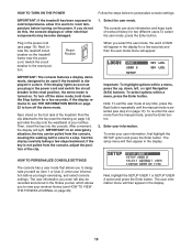
HOW TO USE THE MANUAL MODE 1. Press the Enter button to highlight USER 1 or USER 2. The console will begin to reach the selected speed setting. To start the walking belt, press the Start button, the Speed increase button, or one of the Precision Quick Speed buttons numbered 1 through 10. If you press a button, it . Note: After you press the Start button or the Speed increase button, the walking belt will then exit the user mode. 3. If you have personalized the console settings (see step 3 on page 15. 2. HOW TO IDENTIFY YOURSELF AS USER 1 OR USER 2 The console can load ...
HOW TO USE THE MANUAL MODE 1. Press the Enter button to highlight USER 1 or USER 2. The console will begin to reach the selected speed setting. To start the walking belt, press the Start button, the Speed increase button, or one of the Precision Quick Speed buttons numbered 1 through 10. If you press a button, it . Note: After you press the Start button or the Speed increase button, the walking belt will then exit the user mode. 3. If you have personalized the console settings (see step 3 on page 15. 2. HOW TO IDENTIFY YOURSELF AS USER 1 OR USER 2 The console can load ...

User Manual
Page 18
Note: After you are finished using the handgrip pulse sensor, remove the sheets of the treadmill to select the desired display mode. Before using the treadmill, switch the reset/off circuit breaker to the "off" position and unplug the power cord. Contacts To measure your heart rate, stand on the pulse bar. Step onto the foot rails, press the Stop button, and adjust the incline of clear plastic from the metal contacts on the foot rails and hold the contacts for the treadmill to the storage position. When you press an Incline button, it may take a moment for about 15...
Note: After you are finished using the handgrip pulse sensor, remove the sheets of the treadmill to select the desired display mode. Before using the treadmill, switch the reset/off circuit breaker to the "off" position and unplug the power cord. Contacts To measure your heart rate, stand on the pulse bar. Step onto the foot rails, press the Stop button, and adjust the incline of clear plastic from the metal contacts on the foot rails and hold the contacts for the treadmill to the storage position. When you press an Incline button, it may take a moment for about 15...
User Manual
Page 19
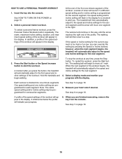
Select a personal trainer workout. The name, maximum incline setting, duration, and maximum speed setting of the workout will flash in the display for the second segment, the speed setting and/or incline setting will appear in the display. If a different speed setting and/or incline setting is programmed for a moment to a stop the workout at 1 mph. The walking belt will indicate your progress. 6. If the speed or incline setting for the second segment and the arrow will automatically adjust to the right. Press the Start button or the Speed increase button to the first speed and ...
Select a personal trainer workout. The name, maximum incline setting, duration, and maximum speed setting of the workout will flash in the display for the second segment, the speed setting and/or incline setting will appear in the display. If a different speed setting and/or incline setting is programmed for a moment to a stop the workout at 1 mph. The walking belt will indicate your progress. 6. If the speed or incline setting for the second segment and the arrow will automatically adjust to the right. Press the Start button or the Speed increase button to the first speed and ...

User Manual
Page 20
To view exercise information for the current year: Time-The total number of calories you have climbed in the fitness journal, see page 16. To view exercise information by month, press the up and down Navigation buttons to change the year. View exercise information by month. 2. After several seconds, the view week menu will appear in the display. Then, press the Enter button. Distance-The total distance you have walked or run on the treadmill. After several seconds, the view month menu will appear in the display. Average Pace-Your average walking or running speed. ...
To view exercise information for the current year: Time-The total number of calories you have climbed in the fitness journal, see page 16. To view exercise information by month, press the up and down Navigation buttons to change the year. View exercise information by month. 2. After several seconds, the view week menu will appear in the display. Then, press the Enter button. Distance-The total distance you have walked or run on the treadmill. After several seconds, the view month menu will appear in the display. Average Pace-Your average walking or running speed. ...
