

English Manual
Page 1
... parts, we will provide immediate assistance, free of charge. Save this equipment. USER'S MANUAL Visit our website at www.proform.com new products, prizes, fitness tips, and much more! Serial Number Decal QUESTIONS? If you have questions, or if there are committed to providing complete customer satisfaction. The serial number is found in the space above. TO AVOID DELAYS, PLEASE CALL DIRECT...
... parts, we will provide immediate assistance, free of charge. Save this equipment. USER'S MANUAL Visit our website at www.proform.com new products, prizes, fitness tips, and much more! Serial Number Decal QUESTIONS? If you have questions, or if there are committed to providing complete customer satisfaction. The serial number is found in the space above. TO AVOID DELAYS, PLEASE CALL DIRECT...
English Manual
Page 2
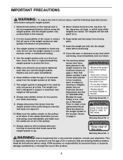
Remove the PART IDENTIFICATION CHART and PART LIST/EXPLODED DRAWING before beginning assembly. PROFORM is a registered trademark of this manual. TABLE OF CONTENTS IMPORTANT PRECAUTIONS 3 BEFORE YOU BEGIN 4 ASSEMBLY 5 CABLE DIAGRAM 21 ADJUSTMENTS 22 WEIGHT RESISTANCE CHART 24 TROUBLESHOOTING AND MAINTENANCE 25 EXERCISE GUIDELINES 26 ORDERING REPLACEMENT PARTS Back Cover LIMITED WARRANTY Back Cover Note: A PART IDENTIFICATION CHART and a PART LIST/EXPLODED DRAWING are attached in the center of ICON Health & Fitness, Inc. 2
Remove the PART IDENTIFICATION CHART and PART LIST/EXPLODED DRAWING before beginning assembly. PROFORM is a registered trademark of this manual. TABLE OF CONTENTS IMPORTANT PRECAUTIONS 3 BEFORE YOU BEGIN 4 ASSEMBLY 5 CABLE DIAGRAM 21 ADJUSTMENTS 22 WEIGHT RESISTANCE CHART 24 TROUBLESHOOTING AND MAINTENANCE 25 EXERCISE GUIDELINES 26 ORDERING REPLACEMENT PARTS Back Cover LIMITED WARRANTY Back Cover Note: A PART IDENTIFICATION CHART and a PART LIST/EXPLODED DRAWING are attached in the center of ICON Health & Fitness, Inc. 2
English Manual
Page 3
... the press arm, leg lever, lat bar, leg press, ab strap, or ankle strap while weights are adequately informed of the owner to be used by or through Friday, 6 a.m. Always disconnect the lat bar from moving parts. 14. Keep hands and feet away from the weight system when performing an exercise that decals number 2 and 3 have been placed on the foot plate when performing an exercise that all users of the weight system...
... the press arm, leg lever, lat bar, leg press, ab strap, or ankle strap while weights are adequately informed of the owner to be used by or through Friday, 6 a.m. Always disconnect the lat bar from moving parts. 14. Keep hands and feet away from the weight system when performing an exercise that decals number 2 and 3 have been placed on the foot plate when performing an exercise that all users of the weight system...
English Manual
Page 4
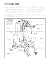
... manual). and familiarize yourself with the parts that are labeled. Shroud Backrest Lat Bar High Pulley Station Warning Decal No. 2 AB Pulley Station Warning Decal No. 1 Press/Fly Arm Weight Stack Seat Warning Decal No. 3 Leg Press Curl Pad Leg Lever Low Pulley Station Foot Plate Warning Decal No. 2 4 Whether your goal is PFSY69520. Mountain Time (excluding holidays). The serial number can be found on a decal attached...
... manual). and familiarize yourself with the parts that are labeled. Shroud Backrest Lat Bar High Pulley Station Warning Decal No. 2 AB Pulley Station Warning Decal No. 1 Press/Fly Arm Weight Stack Seat Warning Decal No. 3 Leg Press Curl Pad Leg Lever Low Pulley Station Foot Plate Warning Decal No. 2 4 Whether your goal is PFSY69520. Mountain Time (excluding holidays). The serial number can be found on a decal attached...
English Manual
Page 5
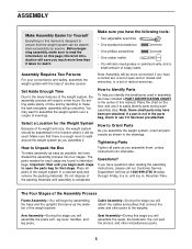
... need grease or petroleum jelly, and a small amount of this manual. Make sure you have included a PART IDENTIFICATION CHART in the center of soapy water. Select a Location for the Weight System Because of open the parts bag for that connect the arms and other miscellaneous parts. 5 Note: Assembly will be used in assembly, we have a socket set, a set of its weight and size, the weight system should be assembled in the location...
... need grease or petroleum jelly, and a small amount of this manual. Make sure you have included a PART IDENTIFICATION CHART in the center of soapy water. Select a Location for the Weight System Because of open the parts bag for that connect the arms and other miscellaneous parts. 5 Note: Assembly will be used in assembly, we have a socket set, a set of its weight and size, the weight system should be assembled in the location...
English Manual
Page 6
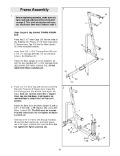
...). Attach the Main Upright (3) to the Main Upright (3) with the two indicated 3/8" x 3 3/4" Carriage Bolts (52) and two 3/8" Nylon Locknuts (50). Press a 2" x 3" Inner Cap (24) into the indicated holes in the indicated locations. Press two 2" Square Inner Caps (33) into the ends of the Base (8). Slide two 5/16" x 3" Bolts (78) through the Base (8) and the Main Upright (3), and hand tighten two...
...). Attach the Main Upright (3) to the Main Upright (3) with the two indicated 3/8" x 3 3/4" Carriage Bolts (52) and two 3/8" Nylon Locknuts (50). Press a 2" x 3" Inner Cap (24) into the indicated holes in the indicated locations. Press two 2" Square Inner Caps (33) into the ends of the Base (8). Slide two 5/16" x 3" Bolts (78) through the Base (8) and the Main Upright (3), and hand tighten two...
English Manual
Page 8
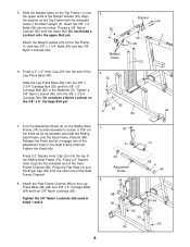
... the Seat Frame Channel. Attach the Weight Guides (23) to the Leg Press Base (84) with two 3/8" x 1 3/4" Bolts (60) and two 3/8" Nylon Locknuts (50). Press a 2" Square Inner Cap (33) into the holes. Press the Flat Plate (4) and the Angle Cap (99) onto the other end of the adjustment holes in the Main Upright (3). Tighten the 3/8" Nylon Locknuts (50) used in the Stabilizer (5). Press a 2" x 3" Inner...
... the Seat Frame Channel. Attach the Weight Guides (23) to the Leg Press Base (84) with two 3/8" x 1 3/4" Bolts (60) and two 3/8" Nylon Locknuts (50). Press a 2" Square Inner Cap (33) into the holes. Press the Flat Plate (4) and the Angle Cap (99) onto the other end of the adjustment holes in the Main Upright (3). Tighten the 3/8" Nylon Locknuts (50) used in the Stabilizer (5). Press a 2" x 3" Inner...
English Manual
Page 10
... the handle. Lubricate the Bolt with the Bolt, Washers, and Locknut. Repeat this step with a 5/16" x 3" Bolt (78), three 5/16" Washers (80), and a 5/16" Nylon Locknut (81). Attach the Leg Lever Lock (11) to the Press Frame (12) with soapy water. Do not overtighten the Bolt and Locknut; Attach the Left Press/Fly Arm (49) to the front leg of the Press Frame (12...
... the handle. Lubricate the Bolt with the Bolt, Washers, and Locknut. Repeat this step with a 5/16" x 3" Bolt (78), three 5/16" Washers (80), and a 5/16" Nylon Locknut (81). Attach the Leg Lever Lock (11) to the Press Frame (12) with soapy water. Do not overtighten the Bolt and Locknut; Attach the Left Press/Fly Arm (49) to the front leg of the Press Frame (12...

English Manual
Page 11
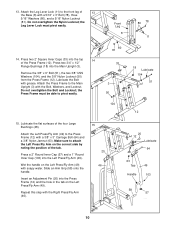
Attach the Pulley and a Cable Trap (44) to hold the Cable in the direction shown, and that the Cable Trap (44) is positioned to the Rear Leg Press Upright (97) with a 3/8" x 3 3/4" Bolt (92), a 3/8" Washer (55), and a 3/8" Nylon Locknut (50). Open the parts bags labeled "CABLE ASSEMBLY" and "4 PULLEYS." Wrap the Leg Press Cable (76) around a 4" Pulley (35). Be sure that the Cable Trap (44) is positioned to the Leg Press Base (84) with a 3/8" x 3 3/4" Bolt (92...
Attach the Pulley and a Cable Trap (44) to hold the Cable in the direction shown, and that the Cable Trap (44) is positioned to the Rear Leg Press Upright (97) with a 3/8" x 3 3/4" Bolt (92), a 3/8" Washer (55), and a 3/8" Nylon Locknut (50). Open the parts bags labeled "CABLE ASSEMBLY" and "4 PULLEYS." Wrap the Leg Press Cable (76) around a 4" Pulley (35). Be sure that the Cable Trap (44) is positioned to the Leg Press Base (84) with a 3/8" x 3 3/4" Bolt (92...
English Manual
Page 12
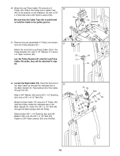
...) is positioned to hold the Cable in step 29. 25 91 71 76 22. Remove the pre-assembled 4" Pulley (not shown) 21 from the Pulley Bracket (91). Feed almost all of the Leg Press Cable (76) to the bracket on the Stabilizer (5) with a 1/4" Washer (71) and a 1/4" Nylon Locknut (25). Tighten a 3/8" Nylon Jamnut (63) onto the Bolt. 73 35 3 42 63 55...
...) is positioned to hold the Cable in step 29. 25 91 71 76 22. Remove the pre-assembled 4" Pulley (not shown) 21 from the Pulley Bracket (91). Feed almost all of the Leg Press Cable (76) to the bracket on the Stabilizer (5) with a 1/4" Washer (71) and a 1/4" Nylon Locknut (25). Tighten a 3/8" Nylon Jamnut (63) onto the Bolt. 73 35 3 42 63 55...
English Manual
Page 17
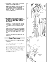
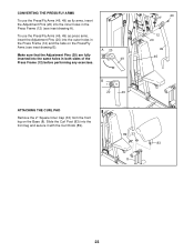
... Cable (73). Thread the 1/2" Plain Nut (68) part way onto the bolt at the end of the pulleys and that they are tight. Open the parts bag labeled "ARM AND SEAT ASSEMBLY." Release the Knob and let it out as far as possible. Route the end of the adjustment holes in the Main Upright (3) with four 1/4" x 3/4" Bolts (17). Attach the Pulley inside the slot in the Seat Upright...
... Cable (73). Thread the 1/2" Plain Nut (68) part way onto the bolt at the end of the pulleys and that they are tight. Open the parts bag labeled "ARM AND SEAT ASSEMBLY." Release the Knob and let it out as far as possible. Route the end of the adjustment holes in the Main Upright (3) with four 1/4" x 3/4" Bolts (17). Attach the Pulley inside the slot in the Seat Upright...
English Manual
Page 20
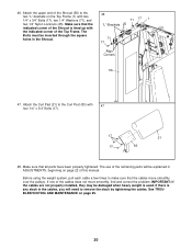
... of the cables does not move smoothly over the pulleys. Attach the Curl Pad (21) to remove the slack by tightening the cables. If one of this manual. The use of the Shroud is used. See TROUBLESHOOTING AND MAINTENANCE on the Top Frame (1) with 47 four 1/4" x 3/4" Bolts (17). 17 21 17 83 48. Make sure that the indicated corner of the remaining parts will...
... of the cables does not move smoothly over the pulleys. Attach the Curl Pad (21) to remove the slack by tightening the cables. If one of this manual. The use of the Shroud is used. See TROUBLESHOOTING AND MAINTENANCE on the Top Frame (1) with 47 four 1/4" x 3/4" Bolts (17). 17 21 17 83 48. Make sure that the indicated corner of the remaining parts will...
English Manual
Page 22
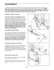
.... Use the WEIGHT RESISTANCE CHART on the Leg Lever. 13 9 37 29 11 28 22 Pull out the Knob as far as an exercise is performed, the effectiveness of the exercise will be changed from the weight setting. Release the Knob so that the accessories are in the correct starting position for the exercise to be attached to the cable at the desired pulley station with a Cable Clip...
.... Use the WEIGHT RESISTANCE CHART on the Leg Lever. 13 9 37 29 11 28 22 Pull out the Knob as far as an exercise is performed, the effectiveness of the exercise will be changed from the weight setting. Release the Knob so that the accessories are in the correct starting position for the exercise to be attached to the cable at the desired pulley station with a Cable Clip...
English Manual
Page 23
... the Adjustment Pins (20) are fully inserted into the front leg and secure it with the Curl Knob (89). 89 33 83 8 23 Slide the Curl Post (83) into the same holes in both sides of the 49 Press Frame (12) before performing any exercises. 20 12 20 49 46 B 20 49 ATTACHING THE CURL PAD Remove the...
... the Adjustment Pins (20) are fully inserted into the front leg and secure it with the Curl Knob (89). 89 33 83 8 23 Slide the Curl Post (83) into the same holes in both sides of the 49 Press Frame (12) before performing any exercises. 20 12 20 49 46 B 20 49 ATTACHING THE CURL PAD Remove the...
English Manual
Page 24
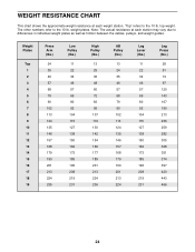
... 196 208 219 231 Leg Press (lbs.) 28 51 74 97 120 143 167 190 213 236 259 282 305 328 351 374 397 420 443 466 24 top weight. weight plates. The other numbers refer to the 10 lb. Note: The actual resistance at each station may... vary due to differences in individual weight plates as well as friction between the cables, pulleys, and weight guides. "Top" refers to the 10 lb. WEIGHT RESISTANCE CHART This chart shows the approximate weight resistance at each weight station...
... 196 208 219 231 Leg Press (lbs.) 28 51 74 97 120 143 167 190 213 236 259 282 305 328 351 374 397 420 443 466 24 top weight. weight plates. The other numbers refer to the 10 lb. Note: The actual resistance at each station may... vary due to differences in individual weight plates as well as friction between the cables, pulleys, and weight guides. "Top" refers to the 10 lb. WEIGHT RESISTANCE CHART This chart shows the approximate weight resistance at each weight station...

English Manual
Page 25
... of holes with the Bolt and Nylon Jamnut. Re-attach the Pulley and Cable Trap to slip off the pulleys, the cable may have become twisted. Note: If a cable tends to the lower set of the High Cable (73). Do not use the weight system. TROUBLESHOOTING AND MAINTENANCE Make sure all parts are properly tightened each time you use solvents. If a cable needs to be cleaned using a damp cloth and mild...
... of holes with the Bolt and Nylon Jamnut. Re-attach the Pulley and Cable Trap to slip off the pulleys, the cable may have become twisted. Note: If a cable tends to the lower set of the High Cable (73). Do not use the weight system. TROUBLESHOOTING AND MAINTENANCE Make sure all parts are properly tightened each time you use solvents. If a cable needs to be cleaned using a damp cloth and mild...
English Manual
Page 26
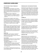
... each exercise, and moving only the appropriate parts of the body. Never hold your body's signals. Exhale during the exertion stage of each set . Complete as possible without discomfort. EXERCISE GUIDELINES THE FOUR BASIC TYPES OF WORKOUTS PERSONALIZING YOUR EXERCISE PROGRAM Muscle Building To increase the size and strength of your muscles, push them to a moderate percentage of their maximum capacity. You...
... each exercise, and moving only the appropriate parts of the body. Never hold your body's signals. Exhale during the exertion stage of each set . Complete as possible without discomfort. EXERCISE GUIDELINES THE FOUR BASIC TYPES OF WORKOUTS PERSONALIZING YOUR EXERCISE PROGRAM Muscle Building To increase the size and strength of your muscles, push them to a moderate percentage of their maximum capacity. You...
English Manual
Page 27
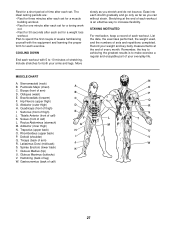
.... Record your everyday life. Biceps (front of leg) W. Rectus Abdominus (stomach) G M. Gluteus Medius (hip) U. Hamstring (back of arm) B D. Ease into each workout with the equipment and learning the proper form for each set for both your arms and legs. List the date, the exercises performed, the weight used, and the numbers of calf) F L L. Pectoralis Major (chest) A C. Abductor (outer thigh) D H. Adductor (inner thigh) M N. Latissimus...
.... Record your everyday life. Biceps (front of leg) W. Rectus Abdominus (stomach) G M. Gluteus Medius (hip) U. Hamstring (back of arm) B D. Ease into each workout with the equipment and learning the proper form for each set for both your arms and legs. List the date, the exercises performed, the weight used, and the numbers of calf) F L L. Pectoralis Major (chest) A C. Abductor (outer thigh) D H. Adductor (inner thigh) M N. Latissimus...
English Manual
Page 31
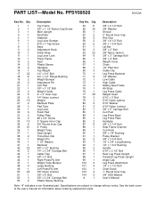
... Sliding Seat Frame Ab Strap Leg Press Cable Weight Insert 5/16" x 3" Bolt 5/16" Nylon Jamnut 5/16" Washer 5/16" Nylon Locknut 3/8" x 5" Carriage Bolt Curl Post Leg Press Base Leg Press Plate Handgrip 3/8" x 3 1/4" Bolt Seat Frame Channel Curl Knob 5/8" x 1/4" Bushing Pulley Bracket 3/8" x 3 3/4" Bolt 1/2" x 3/4" Long Bushing 1/2" x 1 3/4" Bushing Handle 5/16" x 2 1/2" Bolt Rear Leg Press Upright Forward Leg Press Upright Angle Cap Leg Press Attachment 1/4" x 1 1/2" Bolt Chart Decal 1" Round Inner Cap 3/8" USS Washer User's Manual Note: "#" indicates a non-illustrated part. Specifications are...
... Sliding Seat Frame Ab Strap Leg Press Cable Weight Insert 5/16" x 3" Bolt 5/16" Nylon Jamnut 5/16" Washer 5/16" Nylon Locknut 3/8" x 5" Carriage Bolt Curl Post Leg Press Base Leg Press Plate Handgrip 3/8" x 3 1/4" Bolt Seat Frame Channel Curl Knob 5/8" x 1/4" Bushing Pulley Bracket 3/8" x 3 3/4" Bolt 1/2" x 3/4" Long Bushing 1/2" x 1 3/4" Bushing Handle 5/16" x 2 1/2" Bolt Rear Leg Press Upright Forward Leg Press Upright Angle Cap Leg Press Attachment 1/4" x 1 1/2" Bolt Chart Decal 1" Round Inner Cap 3/8" USS Washer User's Manual Note: "#" indicates a non-illustrated part. Specifications are...
English Manual
Page 33
... do not allow limitations on how long an implied warranty lasts. The MODEL NUMBER of this manual). products used as store display models. This warranty does not extend to state. This warranty gives you . until 6 p.m. The SERIAL NUMBER of the product (see the PART LIST and EXPLODED DRAWING in workmanship and material, under normal use , costs of removal or installation or other warranty beyond that specifically set forth herein. Accordingly...
... do not allow limitations on how long an implied warranty lasts. The MODEL NUMBER of this manual). products used as store display models. This warranty does not extend to state. This warranty gives you . until 6 p.m. The SERIAL NUMBER of the product (see the PART LIST and EXPLODED DRAWING in workmanship and material, under normal use , costs of removal or installation or other warranty beyond that specifically set forth herein. Accordingly...


