

English Manual
Page 2
Apply the decal in the location shown. PROFORM is a registered trademark of ICON Health & Fitness, Inc. 2 Note: The decal(s) may not be shown at actual size. IFIT is missing or illegible, see the ... decal(s). If a decal is a registered trademark of ICON Health & Fitness, Inc. TABLE OF CONTENTS WARNING DECAL PLACEMENT 2 IMPORTANT PRECAUTIONS 3 BEFORE YOU BEGIN 5 PART IDENTIFICATION CHART 6 ASSEMBLY 7 HOW TO USE THE EXERCISE BIKE 14 MAINTENANCE AND TROUBLESHOOTING 19 FCC INFORMATION 20 EXERCISE GUIDELINES 21 PART LIST 22 EXPLODED DRAWING 23 ORDERING REPLACEMENT...
Apply the decal in the location shown. PROFORM is a registered trademark of ICON Health & Fitness, Inc. 2 Note: The decal(s) may not be shown at actual size. IFIT is missing or illegible, see the ... decal(s). If a decal is a registered trademark of ICON Health & Fitness, Inc. TABLE OF CONTENTS WARNING DECAL PLACEMENT 2 IMPORTANT PRECAUTIONS 3 BEFORE YOU BEGIN 5 PART IDENTIFICATION CHART 6 ASSEMBLY 7 HOW TO USE THE EXERCISE BIKE 14 MAINTENANCE AND TROUBLESHOOTING 19 FCC INFORMATION 20 EXERCISE GUIDELINES 21 PART LIST 22 EXPLODED DRAWING 23 ORDERING REPLACEMENT...

English Manual
Page 6
Note: If a part is not in parentheses below to see if it has been preassembled. Extra parts may be included. PART IDENTIFICATION CHART Use the drawings below each drawing is the key number of the part, from the PART LIST near the end of this manual. The number following the key number is the quantity needed for assembly. SMcr4exw1(25m7)m-2 SSMcer4elf-xwta1(p56pm3i)nm-g4 M6 x (4501m)-m10Screw SMcr8exw1(66m0)m-4 SMcr8exw1(84m2)m-2 M8 x 3(86m1)m-4Screw M10 x (6484m)-m4 Screw 6 The number in the hardware kit, check to identify the small parts needed for assembly.
Note: If a part is not in parentheses below to see if it has been preassembled. Extra parts may be included. PART IDENTIFICATION CHART Use the drawings below each drawing is the key number of the part, from the PART LIST near the end of this manual. The number following the key number is the quantity needed for assembly. SMcr4exw1(25m7)m-2 SSMcer4elf-xwta1(p56pm3i)nm-g4 M6 x (4501m)-m10Screw SMcr8exw1(66m0)m-4 SMcr8exw1(84m2)m-2 M8 x 3(86m1)m-4Screw M10 x (6484m)-m4 Screw 6 The number in the hardware kit, check to identify the small parts needed for assembly.

English Manual
Page 7
Go to www.proform.com/registration on your computer and register your product. 1 • activates your product. 2. ASSEMBLY • To hire an authorized service technician to assemble this manual) and register your warranty • saves you time if you ever need to contact Customer Care •... until you have Internet access, call Customer Care (see the front cover of this product, call 1-800-445-2480. • Assembly requires two persons. • Place all assembly steps. • Left parts are marked "L" or "Left" and right parts are marked "R" or "Right." • To ...
Go to www.proform.com/registration on your computer and register your product. 1 • activates your product. 2. ASSEMBLY • To hire an authorized service technician to assemble this manual) and register your warranty • saves you time if you ever need to contact Customer Care •... until you have Internet access, call Customer Care (see the front cover of this product, call 1-800-445-2480. • Assembly requires two persons. • Place all assembly steps. • Left parts are marked "L" or "Left" and right parts are marked "R" or "Right." • To ...

English Manual
Page 13
... Right Pedal (29) clockwise into the Left Crank Arm (not shown). IMPORTANT: You must turn the Left Pedal counterclockwise to make sure that it is assembled correctly and that all parts are properly tightened before you use the exercise bike. After the exercise bike is... assembled, inspect it to attach it functions properly. Firmly tighten the Left Pedal (not shown) counterclockwise into the right arm of the strap onto the tab ...
... Right Pedal (29) clockwise into the Left Crank Arm (not shown). IMPORTANT: You must turn the Left Pedal counterclockwise to make sure that it is assembled correctly and that all parts are properly tightened before you use the exercise bike. After the exercise bike is... assembled, inspect it to attach it functions properly. Firmly tighten the Left Pedal (not shown) counterclockwise into the right arm of the strap onto the tab ...

English Manual
Page 15
... heart rate using the console, make your workouts more effective and enjoyable. Note: Before using the handgrip heart rate monitor. To use a preset workout, see assembly step 11 on the display, remove the plastic. 15 To use the sound system, see page 18. As you can even connect your favorite music...
... heart rate using the console, make your workouts more effective and enjoyable. Note: Before using the handgrip heart rate monitor. To use a preset workout, see assembly step 11 on the display, remove the plastic. 15 To use the sound system, see page 18. As you can even connect your favorite music...

English Manual
Page 19
...) passes the Reed Switch (35) repeatedly. When the reed switch is used. MAINTENANCE AND TROUBLESHOOTING MAINTENANCE Regular maintenance is important for battery replacement instructions. See assembly step 11 on page 12 for optimal performance and to or away from the console and keep liquids away from the Magnet, and then retighten.... IMPORTANT: To avoid damage to the console, keep the console out of low batteries. Turn the Crank (40) until the console displays correct feedback. See assembly step 5 on page 17.
...) passes the Reed Switch (35) repeatedly. When the reed switch is used. MAINTENANCE AND TROUBLESHOOTING MAINTENANCE Regular maintenance is important for battery replacement instructions. See assembly step 11 on page 12 for optimal performance and to or away from the console and keep liquids away from the Magnet, and then retighten.... IMPORTANT: To avoid damage to the console, keep the console out of low batteries. Turn the Crank (40) until the console displays correct feedback. See assembly step 5 on page 17.
English Manual
Page 20
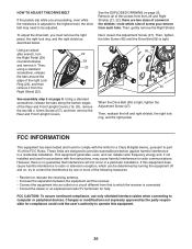
... can be adjusted. Using an adjustable wrench, turn the Right Pedal (29) counterclockwise and remove it from the Right Shield (22). 22 29 23 See assembly step 5 on a circuit different from each hole. Then, reattach the left and right shields, the right lock ring, and the right pedal. FCC CAUTION: To...
... can be adjusted. Using an adjustable wrench, turn the Right Pedal (29) counterclockwise and remove it from the Right Shield (22). 22 29 23 See assembly step 5 on a circuit different from each hole. Then, reattach the left and right shields, the right lock ring, and the right pedal. FCC CAUTION: To...
English Manual
Page 22
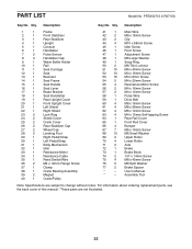
... x 16mm Screw M6 Small Washer Upper Roller Lower Roller Axle Brake Brake Block 1/4" x 14mm Screw M8 x 45mm Screw M6 Split Washer Brake Spacer User's Manual Assembly Tool Note: Specifications are not illustrated. 22 For information about ordering replacement parts, see the back cover of this manual. *These parts are subject to... Leveling Foot Right Pedal/Strap Left Pedal/Strap Eddy Mechanism Idler Resistance Motor Resistance Cable Reed Switch/Wire M4 x 12mm Flange Screw Clamp Crank Bearing Assembly Magnet Crank/Pulley Key No.
... x 16mm Screw M6 Small Washer Upper Roller Lower Roller Axle Brake Brake Block 1/4" x 14mm Screw M8 x 45mm Screw M6 Split Washer Brake Spacer User's Manual Assembly Tool Note: Specifications are not illustrated. 22 For information about ordering replacement parts, see the back cover of this manual. *These parts are subject to... Leveling Foot Right Pedal/Strap Left Pedal/Strap Eddy Mechanism Idler Resistance Motor Resistance Cable Reed Switch/Wire M4 x 12mm Flange Screw Clamp Crank Bearing Assembly Magnet Crank/Pulley Key No.


