
Service Manual
Page 1
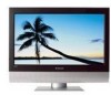
North America TLA-04641C, 4641-TLXB SERVICE MANUAL Bezel covers vary by model 20070605 2007 LCD Models -
North America TLA-04641C, 4641-TLXB SERVICE MANUAL Bezel covers vary by model 20070605 2007 LCD Models -
Service Manual
Page 2
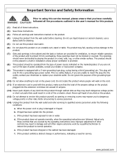
...people will walk on the cord. (11) If an extension cord is a safety feature, if you are provided for service. . 2 www.polaroid.com Adjust only those openings must not be blocked or covered. The openings should be blocked by a qualified technician to restore the product to ...a plug having a third (grounding) pin. d. Important Service and Safety Information Prior to using this service manual, please ensure that you have carefully followed all the procedures outlined in the user's manual for cleaning. (5) Do not use this product near water. (6) Do not place this product on an ...
...people will walk on the cord. (11) If an extension cord is a safety feature, if you are provided for service. . 2 www.polaroid.com Adjust only those openings must not be blocked or covered. The openings should be blocked by a qualified technician to restore the product to ...a plug having a third (grounding) pin. d. Important Service and Safety Information Prior to using this service manual, please ensure that you have carefully followed all the procedures outlined in the user's manual for cleaning. (5) Do not use this product near water. (6) Do not place this product on an ...
Service Manual
Page 5
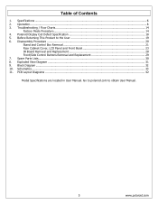
...14 Factory Mode Procedure...14 4. Schematics...33 11. Go to polaroid.com to the User 19 6. Polaroid Display Cell Defect Specification 18 5. Disassembly Procedure ...20 Stand and Control Box Removal 21 Rear Cabinet Cover, LCD Panel and Front Bezel 23 IR Board Removal and Replacement 28 ...Front/Side Control Buttons Removal and Replacement 29 7. Spare Parts Lists...30 8. Operation...8 3. Exploded View Diagram ...31 9. Before Returning This Product to obtain User Manual. 5 www.polaroid.com PCB ...
...14 Factory Mode Procedure...14 4. Schematics...33 11. Go to polaroid.com to the User 19 6. Polaroid Display Cell Defect Specification 18 5. Disassembly Procedure ...20 Stand and Control Box Removal 21 Rear Cabinet Cover, LCD Panel and Front Bezel 23 IR Board Removal and Replacement 28 ...Front/Side Control Buttons Removal and Replacement 29 7. Spare Parts Lists...30 8. Operation...8 3. Exploded View Diagram ...31 9. Before Returning This Product to obtain User Manual. 5 www.polaroid.com PCB ...

User Guide
Page 2
All rights reserved. This TV incorporates High-Definition Multimedia Interface (HDMITM) technology. Changes, technical inaccuracies, and typographic errors will be corrected in the instruction manual. Presence of this document. HDMI, the HDMI logo and High-Definition ...Multimedia Interface are trademarks or registered trademarks of properly, have potential adverse effects on the environment and human health. For service, support and warranty information, visit www.polaroid...
All rights reserved. This TV incorporates High-Definition Multimedia Interface (HDMITM) technology. Changes, technical inaccuracies, and typographic errors will be corrected in the instruction manual. Presence of this document. HDMI, the HDMI logo and High-Definition ...Multimedia Interface are trademarks or registered trademarks of properly, have potential adverse effects on the environment and human health. For service, support and warranty information, visit www.polaroid...

User Guide
Page 4
... This symbol is an important feature. This equipment and recommended cart or stand should be observed in the installation, use, servicing and maintenance of this manual completely, and keep it nearby for future reference. Quick stops, excessive force, and uneven surfaces may cause the equipment and cart/stand to install a grounding...
... This symbol is an important feature. This equipment and recommended cart or stand should be observed in the installation, use, servicing and maintenance of this manual completely, and keep it nearby for future reference. Quick stops, excessive force, and uneven surfaces may cause the equipment and cart/stand to install a grounding...

User Guide
Page 9
... you need to set up and operate the LCD TV in the package. Package Contents Chapter 1 Introducing the LCD TV Make sure all you are included. LCD TV Bottom Stand / Screw Driver and Screws 4 ENGLISH Remote Control/ AAA Batteries x 2 SET UP TV CAB/ SAT DVD AUX SLEEP DVD MENU VOL... Card User's Manual Quick Start Guide Stand Assembly Guide Remote control Guide These items are included in its basic configuration. Make sure all of the above contents are all of the following contents are missing any items, please contact the Polaroid customer service department...
... you need to set up and operate the LCD TV in the package. Package Contents Chapter 1 Introducing the LCD TV Make sure all you are included. LCD TV Bottom Stand / Screw Driver and Screws 4 ENGLISH Remote Control/ AAA Batteries x 2 SET UP TV CAB/ SAT DVD AUX SLEEP DVD MENU VOL... Card User's Manual Quick Start Guide Stand Assembly Guide Remote control Guide These items are included in its basic configuration. Make sure all of the above contents are all of the following contents are missing any items, please contact the Polaroid customer service department...

User Guide
Page 17
... any AC power cords to wall outlets until all other connections are more important than those for a black & white TV reception. ENGLISH Chapter 2 Installing the LCD TV Chapter 2 Installing the LCD TV Refer to the owner's manual of connection that is provided with the various antenna systems. ■ A 75-ohm system is generally a round cable (not...
... any AC power cords to wall outlets until all other connections are more important than those for a black & white TV reception. ENGLISH Chapter 2 Installing the LCD TV Chapter 2 Installing the LCD TV Refer to the owner's manual of connection that is provided with the various antenna systems. ■ A 75-ohm system is generally a round cable (not...

User Guide
Page 22
.../CABLE VHF/UHF IN AV Cable AUDIO Cable S-VIDEO Cable METHOD A: Use a composite cable to connect the VCR's composite video/audio jacks to the LCD TV's VIDEO2 IN jacks. Connect all AC power sources, before turning on the remote to select VIDEO2( METHOD A), or VIDEO3 (METHOD B). To watch a videotape, press the ...INPUT button on the remote to turn on your VCR and follow the instructions in your VCR's manual. 22 Chapter 2 Installing the LCD TV Connecting a VCR Rear of the LCD TV or other connected equipment.
.../CABLE VHF/UHF IN AV Cable AUDIO Cable S-VIDEO Cable METHOD A: Use a composite cable to connect the VCR's composite video/audio jacks to the LCD TV's VIDEO2 IN jacks. Connect all AC power sources, before turning on the remote to select VIDEO2( METHOD A), or VIDEO3 (METHOD B). To watch a videotape, press the ...INPUT button on the remote to turn on your VCR and follow the instructions in your VCR's manual. 22 Chapter 2 Installing the LCD TV Connecting a VCR Rear of the LCD TV or other connected equipment.

