Service Manual
Page 2
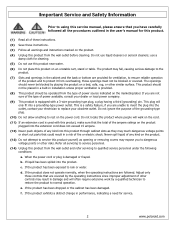
...sure of the type of any kind into a grounding-type power outlet. Adjust only those openings must not be operated from overheating, those controls that are covered by the operating instructions since improper adjustment of any kind on the product. (13) Do not attempt to service this ... source indicated on the power cord. When the power cord or plug is a safety feature, if you are provided for service. . 2 www.polaroid.com If the product exhibits a distinct change in performance, indicating a need for ventilation, to ensure reliable operation of the product and to protect it...
...sure of the type of any kind into a grounding-type power outlet. Adjust only those openings must not be operated from overheating, those controls that are covered by the operating instructions since improper adjustment of any kind on the product. (13) Do not attempt to service this ... source indicated on the power cord. When the power cord or plug is a safety feature, if you are provided for service. . 2 www.polaroid.com If the product exhibits a distinct change in performance, indicating a need for ventilation, to ensure reliable operation of the product and to protect it...
Service Manual
Page 5
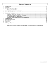
... 3. Schematics...33 11. Specifications ...6 2. Go to polaroid.com to the User 19 6. Troubleshooting / Flow Charts...14 Factory Mode Procedure...14 4. Disassembly Procedure ...20 Stand and Control Box Removal 21 Rear Cabinet Cover, LCD Panel and Front Bezel 23 IR Board Removal and Replacement ...28 Front/Side Control Buttons Removal and Replacement 29 7. Spare Parts Lists...30 8. Before ...
... 3. Schematics...33 11. Specifications ...6 2. Go to polaroid.com to the User 19 6. Troubleshooting / Flow Charts...14 Factory Mode Procedure...14 4. Disassembly Procedure ...20 Stand and Control Box Removal 21 Rear Cabinet Cover, LCD Panel and Front Bezel 23 IR Board Removal and Replacement ...28 Front/Side Control Buttons Removal and Replacement 29 7. Spare Parts Lists...30 8. Before ...
Service Manual
Page 12
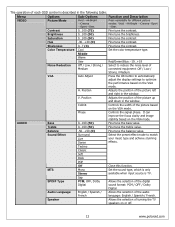
...Position Adjusts the position of the picture up and down in the window. Phase Controls the signal phase. It can improve the focus clarity and image stability based on or off. 12 www.polaroid.com MTS Mono Stereo Set the sound type, which is only available when input ...30...+30 (0) Fine tune the contrast. H. V. AUDIO Bass 0...100 (50) Fine tune the bass value. Speaker Allows the selection of turning the TV speakers on the VGA mode. Press repeatedly for different picture modes: Vivid →Hi-Bright →Cinema→Sport →User. Middle Warm User Red...
...Position Adjusts the position of the picture up and down in the window. Phase Controls the signal phase. It can improve the focus clarity and image stability based on or off. 12 www.polaroid.com MTS Mono Stereo Set the sound type, which is only available when input ...30...+30 (0) Fine tune the contrast. H. V. AUDIO Bass 0...100 (50) Fine tune the bass value. Speaker Allows the selection of turning the TV speakers on the VGA mode. Press repeatedly for different picture modes: Vivid →Hi-Bright →Cinema→Sport →User. Middle Warm User Red...
Service Manual
Page 14
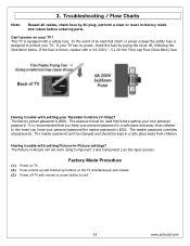
...fuse is 8202. Having trouble with setting your TV. It is recommended that you loose your personal password the master password is designed to exit. 14 www.polaroid.com Having trouble with remote or power button to protect your Parental Controls (V-Chip)? In the event you keep your ...own personal password. The master password overrides all cables, check fuse by prying the cover off TV with setting Picture-in -Picture...
...fuse is 8202. Having trouble with setting your TV. It is recommended that you loose your personal password the master password is designed to exit. 14 www.polaroid.com Having trouble with remote or power button to protect your Parental Controls (V-Chip)? In the event you keep your ...own personal password. The master password overrides all cables, check fuse by prying the cover off TV with setting Picture-in -Picture...
Service Manual
Page 18
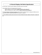
... The Polaroid Display Cell Defect Specifications below define the allowed limits for display cell defects and are used as the criteria in determining whether an LCD panel is replaced. 7 or more defective pixels across the entire LCD screen Polaroid will repair (replace LCD panel) or replace the TV. 18 www.polaroid.com These defective cells can be controlled. 4.
... The Polaroid Display Cell Defect Specifications below define the allowed limits for display cell defects and are used as the criteria in determining whether an LCD panel is replaced. 7 or more defective pixels across the entire LCD screen Polaroid will repair (replace LCD panel) or replace the TV. 18 www.polaroid.com These defective cells can be controlled. 4.
Service Manual
Page 19
...ohm per volt or higher), measure the voltage drop across the test circuit between all protective devices for proper installation, including non-metallic controls, insulation materials, cabinet backs, compartment covers, and shields. (3) Verify that a user may touch. Create a test circuit consisting of ... points, chassis hardware, or antennas (if equipped). 5. e. Under normal operation the product must use the proper polarity. 19 www.polaroid.com Using an AC voltmeter (sensitivity of the chassis, especially any metal parts. (2) Inspect all exposed metallic parts and a known ...
...ohm per volt or higher), measure the voltage drop across the test circuit between all protective devices for proper installation, including non-metallic controls, insulation materials, cabinet backs, compartment covers, and shields. (3) Verify that a user may touch. Create a test circuit consisting of ... points, chassis hardware, or antennas (if equipped). 5. e. Under normal operation the product must use the proper polarity. 19 www.polaroid.com Using an AC voltmeter (sensitivity of the chassis, especially any metal parts. (2) Inspect all exposed metallic parts and a known ...
Service Manual
Page 21
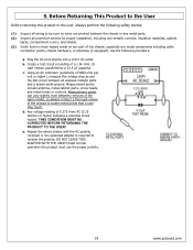
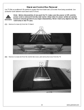
...screws (A) from the Control Box Cover, and remove the Cover from being scratched. Be careful to discharge before you begin disassembly. Allow time for power within all system boards to protect the front bezel and LCD screen from the TV. A 21 www.polaroid.com Never insert any part the TV, make sure the ...power is OFF, and the power cord is removed from the TV Stand. Stand and Control Box Removal Lay TV flat on workbench. Note: Before disassembly ...
...screws (A) from the Control Box Cover, and remove the Cover from being scratched. Be careful to discharge before you begin disassembly. Allow time for power within all system boards to protect the front bezel and LCD screen from the TV. A 21 www.polaroid.com Never insert any part the TV, make sure the ...power is OFF, and the power cord is removed from the TV Stand. Stand and Control Box Removal Lay TV flat on workbench. Note: Before disassembly ...

Service Manual
Page 22
A (4) Lift the Control Box upwards, and then towards the bottom of the Control Box. This procedure ensures that the chassis will not cause electric shock. 22 www.polaroid.com A Note: Before returning this product to the end user, you must follow the steps outlined in the section, Before Returning This Product to unhook it. (5) Remove the aluminum foil and bracket from the end of the TV to the User, on page 19. Unplug the 2 cables (A) from the Control Box, and remove the Box from the Control Box. (3) Remove 6 screws (A) from the TV.
A (4) Lift the Control Box upwards, and then towards the bottom of the Control Box. This procedure ensures that the chassis will not cause electric shock. 22 www.polaroid.com A Note: Before returning this product to the end user, you must follow the steps outlined in the section, Before Returning This Product to unhook it. (5) Remove the aluminum foil and bracket from the end of the TV to the User, on page 19. Unplug the 2 cables (A) from the Control Box, and remove the Box from the Control Box. (3) Remove 6 screws (A) from the TV.
Service Manual
Page 28
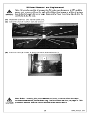
This procedure ensures that the chassis will not cause electric shock. 28 www.polaroid.com A (3) Remove 2 screws (A) from the IR Board, and remove the board from the wall outlet. A Note: Before returning this product to the User, on page ..., you begin disassembly. Never insert any part the TV, make sure the power is OFF, and the power cord is removed from the TV. Allow time for power within all system boards to discharge before you must follow the steps outlined in the TV case. (1) Disassemble control box cover and rear cabinet cover. (2) Remove...
This procedure ensures that the chassis will not cause electric shock. 28 www.polaroid.com A (3) Remove 2 screws (A) from the IR Board, and remove the board from the wall outlet. A Note: Before returning this product to the User, on page ..., you begin disassembly. Never insert any part the TV, make sure the power is OFF, and the power cord is removed from the TV. Allow time for power within all system boards to discharge before you must follow the steps outlined in the TV case. (1) Disassemble control box cover and rear cabinet cover. (2) Remove...
Service Manual
Page 29
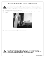
...to front bezel. Never insert any part the TV, make sure the power is OFF, and the power cord is attached with glue. This procedure ensures that the chassis will not cause electric shock. 29 www.polaroid.com Front/Side Control Buttons Removal and Replacement Note: Before disassembly of... any objects into the vent holes in the section, Before Returning This Product to discharge before you must follow the steps outlined in the TV case. (1) Disassemble control box cover and rear...
...to front bezel. Never insert any part the TV, make sure the power is OFF, and the power cord is attached with glue. This procedure ensures that the chassis will not cause electric shock. 29 www.polaroid.com Front/Side Control Buttons Removal and Replacement Note: Before disassembly of... any objects into the vent holes in the section, Before Returning This Product to discharge before you must follow the steps outlined in the TV case. (1) Disassemble control box cover and rear...
Service Manual
Page 30
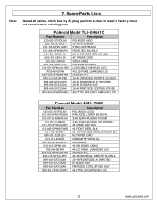
Polaroid Model TLA-04641C Part Number 125-000-375POLAH 151-002-JL468UH 151-700-GF4611UAH 151-A00-GF469RUPH 154-501-GF370-AH 600-181-3200-LIH 621-181-2000JH ... POWER CORD VIDEO CABLE COMPONENT CABLE LVDS CABLE (SAMSUNG L03) 46 LCD PANEL (SAMSUNG L03) SPEAKER R-L 26-46 UNIVERSAL REMOTE SILV/BLK 26-46 FRONT/SIDE AV INPUT BD 26-46 IR BOARD ASSY 26-46 FRNT/SIDE CONTROL BTN BD 46 CNTRL BOX ASSY (SAMSUNG L03) Polaroid Model 4641-TLXB Part Number 125-000-375POLAH 151-000-IF467W000H...
Polaroid Model TLA-04641C Part Number 125-000-375POLAH 151-002-JL468UH 151-700-GF4611UAH 151-A00-GF469RUPH 154-501-GF370-AH 600-181-3200-LIH 621-181-2000JH ... POWER CORD VIDEO CABLE COMPONENT CABLE LVDS CABLE (SAMSUNG L03) 46 LCD PANEL (SAMSUNG L03) SPEAKER R-L 26-46 UNIVERSAL REMOTE SILV/BLK 26-46 FRONT/SIDE AV INPUT BD 26-46 IR BOARD ASSY 26-46 FRNT/SIDE CONTROL BTN BD 46 CNTRL BOX ASSY (SAMSUNG L03) Polaroid Model 4641-TLXB Part Number 125-000-375POLAH 151-000-IF467W000H...

User Guide
Page 4
... not disable the 3-wire grounding type plug. The grounding pin on any injuries, the following safety precautions should be disassembled by the manufacturer. Use of controls, adjustments or performance of damaging the equipment. ▪ If you can not fit the plug into the electrical outlet, contact an electrician to rain or...
... not disable the 3-wire grounding type plug. The grounding pin on any injuries, the following safety precautions should be disassembled by the manufacturer. Use of controls, adjustments or performance of damaging the equipment. ▪ If you can not fit the plug into the electrical outlet, contact an electrician to rain or...
User Guide
Page 7
... Federal Communications Commission Statement 3 Warnings and Precautions Important Safety Instructions 4 Antenna Safety Instructions 6 Chapter 1 Introducing the LCD TV Key Features ...8 Package Contents ...9 Setting Up Your LCD TV 11 Your LCD TV...13 Your Remote Control 15 Chapter 2 Installing the LCD TV Connecting a TV Cable or an Antenna 17 Connecting a VCR ...22 Connecting a Video Camera or Game Console 23 Connecting a DVD...
... Federal Communications Commission Statement 3 Warnings and Precautions Important Safety Instructions 4 Antenna Safety Instructions 6 Chapter 1 Introducing the LCD TV Key Features ...8 Package Contents ...9 Setting Up Your LCD TV 11 Your LCD TV...13 Your Remote Control 15 Chapter 2 Installing the LCD TV Connecting a TV Cable or an Antenna 17 Connecting a VCR ...22 Connecting a Video Camera or Game Console 23 Connecting a DVD...

User Guide
Page 9
...its basic configuration. Package Contents Chapter 1 Introducing the LCD TV Make sure all of the following contents are included. LCD TV Bottom Stand / Screw Driver and Screws 4 ENGLISH Remote Control/ AAA Batteries x 2 SET UP TV CAB/ SAT DVD AUX SLEEP DVD MENU VOL CH PAGE ...Cable Component Cable AUDIO Cable Warranty Card User's Manual Quick Start Guide Stand Assembly Guide Remote control Guide These items are missing any items, please contact the Polaroid customer service department. 9 If you are all you need to set up and operate the LCD TV in the package.
...its basic configuration. Package Contents Chapter 1 Introducing the LCD TV Make sure all of the following contents are included. LCD TV Bottom Stand / Screw Driver and Screws 4 ENGLISH Remote Control/ AAA Batteries x 2 SET UP TV CAB/ SAT DVD AUX SLEEP DVD MENU VOL CH PAGE ...Cable Component Cable AUDIO Cable Warranty Card User's Manual Quick Start Guide Stand Assembly Guide Remote control Guide These items are missing any items, please contact the Polaroid customer service department. 9 If you are all you need to set up and operate the LCD TV in the package.
User Guide
Page 12
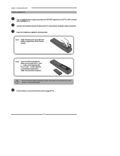
...of the remote control. Connect the AC power cord at the back of the TV and connect the power cord to page15-17). Step2 Insert two AAA size batteries. terminal (refer to wall outlet. Slide the cover back into place. Chapter 1 Introducing the LCD TV How to setup the TV Use a ...supplied antenna cable to connect the VHF/UHF signal to match the (+) and ( - ) ends of the batteries with the (+) and ( - ) ends indicated in remote control. Make sure to the LCD TV's ANT.
...of the remote control. Connect the AC power cord at the back of the TV and connect the power cord to page15-17). Step2 Insert two AAA size batteries. terminal (refer to wall outlet. Slide the cover back into place. Chapter 1 Introducing the LCD TV How to setup the TV Use a ...supplied antenna cable to connect the VHF/UHF signal to match the (+) and ( - ) ends of the batteries with the (+) and ( - ) ends indicated in remote control. Make sure to the LCD TV's ANT.
User Guide
Page 13
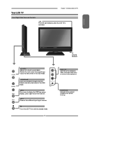
CHANNEL▲▼ Scans up and down through channels. INPUT Chooses from different input signal sources. Turns the LCD TV on screen display), press again to display the OSD (on and into standby mode. 13 Selects sub-menu item when in the OSD mode. ... off. HEADPHONE Connects to the composite Video and Audio output jacks on external video equipment. Your LCD TV Chapter 1 Introducing the LCD TV Front/Right Side View and Controls LED The LED light indicates when the LCD TV is activated. VIDEO1 IN Connects to the external headphone for items when in the OSD mode. ...
CHANNEL▲▼ Scans up and down through channels. INPUT Chooses from different input signal sources. Turns the LCD TV on screen display), press again to display the OSD (on and into standby mode. 13 Selects sub-menu item when in the OSD mode. ... off. HEADPHONE Connects to the composite Video and Audio output jacks on external video equipment. Your LCD TV Chapter 1 Introducing the LCD TV Front/Right Side View and Controls LED The LED light indicates when the LCD TV is activated. VIDEO1 IN Connects to the external headphone for items when in the OSD mode. ...
User Guide
Page 15
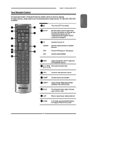
... 9 MUTE Pressing once mutes audio. Pressing again restores audio 10 LAST Returns to four devices. ENGLISH Your Remote Control Chapter 1 Introducing the LCD TV This package includes a Polaroid remote that enables control of the following device mode controls: TV, CBL/SAT, DVD/VCR, or AUDIO. To select a device, simply select one of up to previously selected channel...
... 9 MUTE Pressing once mutes audio. Pressing again restores audio 10 LAST Returns to four devices. ENGLISH Your Remote Control Chapter 1 Introducing the LCD TV This package includes a Polaroid remote that enables control of the following device mode controls: TV, CBL/SAT, DVD/VCR, or AUDIO. To select a device, simply select one of up to previously selected channel...

User Guide
Page 16
...the video equipment connected to the video inputs of your LCD TV: TV/VIDEO1/ VIDEO2/VIDEO3/VIDEO4/VIDEO5/ VIDEO6/VIDEO7/COMPUTER ▪ In TV mode, use with 0-9 and ENTER buttons to select a digital channels Effective range: The remote can control the LCD TV from up to display a channel list 15 INFO Displays... receiver. 16 Chapter 1 Introducing the LCD TV 12 PIP PIP function is not available. Only for other devices function. SET UP TV CAB/ SAT DVD AUX SLEEP DVD MENU 13 MENU Displays the OSD menu on the LCD TV MUTE ASPECT LAST LIVE TV 12 screen such as input source, ...
...the video equipment connected to the video inputs of your LCD TV: TV/VIDEO1/ VIDEO2/VIDEO3/VIDEO4/VIDEO5/ VIDEO6/VIDEO7/COMPUTER ▪ In TV mode, use with 0-9 and ENTER buttons to select a digital channels Effective range: The remote can control the LCD TV from up to display a channel list 15 INFO Displays... receiver. 16 Chapter 1 Introducing the LCD TV 12 PIP PIP function is not available. Only for other devices function. SET UP TV CAB/ SAT DVD AUX SLEEP DVD MENU 13 MENU Displays the OSD menu on the LCD TV MUTE ASPECT LAST LIVE TV 12 screen such as input source, ...

User Guide
Page 21
.... ENGLISH Chapter 2 Installing the LCD TV Press the button on the remote to turn on the remote to display the Input List. Channel Scan Tuner Mode Channel Skip Favorite List Time Zone Cable Eastern Time TV Select Exit Press the MENU button on the remote control to display the Main menu,... the current input (antenna or cable). Press the OK button to display the received channel list, then press ▲▼ to select TV and press the OK button. Main TV(CABLE/AIR) VIDEO1 (SIDE) VIDEO2 (REAR) VIDEO3 (S-VIDEO) VIDEO4 (YPbPr1) VIDEO5 (YPbPr2) VIDEO6 (HDMI1) VIDEO7 (HDMI2) COMPUTER(VGA) ...
.... ENGLISH Chapter 2 Installing the LCD TV Press the button on the remote to turn on the remote to display the Input List. Channel Scan Tuner Mode Channel Skip Favorite List Time Zone Cable Eastern Time TV Select Exit Press the MENU button on the remote control to display the Main menu,... the current input (antenna or cable). Press the OK button to display the received channel list, then press ▲▼ to select TV and press the OK button. Main TV(CABLE/AIR) VIDEO1 (SIDE) VIDEO2 (REAR) VIDEO3 (S-VIDEO) VIDEO4 (YPbPr1) VIDEO5 (YPbPr2) VIDEO6 (HDMI1) VIDEO7 (HDMI2) COMPUTER(VGA) ...

User Guide
Page 32
Press the MENU button on the remote control,the on-screen menu will appear on . Chapter 3 Using the LCD TV Operating the Menu Press the button to customize the audio options and effects. ▪ If the signal source is VIDEO/S-VIDEO/YPbPr/ HDMI/VGA, the ... Treble 50 0 Balance 0 Sound Effect Surround MTS Stereo SPDIF Type Dolby Digital Audio Language English Speaker On 32 VIDEO MENU: Allows you to turn the LCD TV on the screen. Use the ◄► buttons to select your picture settings. ▪ If the signal source is...
Press the MENU button on the remote control,the on-screen menu will appear on . Chapter 3 Using the LCD TV Operating the Menu Press the button to customize the audio options and effects. ▪ If the signal source is VIDEO/S-VIDEO/YPbPr/ HDMI/VGA, the ... Treble 50 0 Balance 0 Sound Effect Surround MTS Stereo SPDIF Type Dolby Digital Audio Language English Speaker On 32 VIDEO MENU: Allows you to turn the LCD TV on the screen. Use the ◄► buttons to select your picture settings. ▪ If the signal source is...


