
Owner's Manual
Page 1
Operating Instructions AUDIO/VIDEO MULTI-CHANNEL RECEIVER
Operating Instructions AUDIO/VIDEO MULTI-CHANNEL RECEIVER
Owner's Manual
Page 2
...THIS (POLARIZED) PLUG WITH AN EXTENSION CORD. D2-4-4-1_EF WARNING - Product Name: AUDIO/VIDEO MULTI-CHANNEL RECEIVER Model Number: VSX-94TXH, VSX-92TXH Responsible Party Name: PIONEER ELECTRONICS SERVICE, INC. D1-4-2-6-1_En NOTE: This equipment has been tested and found to comply with the limits...cord serves as radios and televisions, use shielded cables and connectors for example, when on this device must accept any interference received, including interference that interference will not completely shut off and on a circuit different from the AC outlet when left unused for...
...THIS (POLARIZED) PLUG WITH AN EXTENSION CORD. D2-4-4-1_EF WARNING - Product Name: AUDIO/VIDEO MULTI-CHANNEL RECEIVER Model Number: VSX-94TXH, VSX-92TXH Responsible Party Name: PIONEER ELECTRONICS SERVICE, INC. D1-4-2-6-1_En NOTE: This equipment has been tested and found to comply with the limits...cord serves as radios and televisions, use shielded cables and connectors for example, when on this device must accept any interference received, including interference that interference will not completely shut off and on a circuit different from the AC outlet when left unused for...
Owner's Manual
Page 4
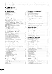
... connections Connecting an iPod 50 Connecting your iPod to the receiver 50 iPod playback 50 Watching photos and video content 51 4 En Please read through these operating instructions so you for buying this Pioneer product. Contents 01 Before you have finished reading the instructions... surround sound 28 Using the Home THX modes 29 Using the Advanced surround effects 29 Listening in the box 6 Ventilation 6 Installing the receiver 6 Loading the batteries 6 02 5 minute guide Introduction to home theater 7 Listening to Surround Sound 7 Automatically setting up for future ...
... connections Connecting an iPod 50 Connecting your iPod to the receiver 50 iPod playback 50 Watching photos and video content 51 4 En Please read through these operating instructions so you for buying this Pioneer product. Contents 01 Before you have finished reading the instructions... surround sound 28 Using the Home THX modes 29 Using the Advanced surround effects 29 Listening in the box 6 Ventilation 6 Installing the receiver 6 Loading the batteries 6 02 5 minute guide Introduction to home theater 7 Listening to Surround Sound 7 Automatically setting up for future ...
Owner's Manual
Page 5
...Making MULTI-ZONE connections 59 Using the MULTI-ZONE controls 60 Connecting an IR receiver 61 Switching components on and off using the 12 volt trigger 61 Using this receiver with a Pioneer plasma display . . . 62 Using the SR+ mode with a Pioneer plasma display. . . 63 Connecting a PC for Advanced MCACC output . ...purposes (such as long-term use for general household purposes. Any failure due to cause cancer and birth defect or other Pioneer components with this unit's sensor 82 13 Additional information Troubleshooting 83 Power 83 No sound 83 Other audio problems 84 Video...
...Making MULTI-ZONE connections 59 Using the MULTI-ZONE controls 60 Connecting an IR receiver 61 Switching components on and off using the 12 volt trigger 61 Using this receiver with a Pioneer plasma display . . . 62 Using the SR+ mode with a Pioneer plasma display. . . 63 Connecting a PC for Advanced MCACC output . ...purposes (such as long-term use for general household purposes. Any failure due to cause cancer and birth defect or other Pioneer components with this unit's sensor 82 13 Additional information Troubleshooting 83 Power 83 No sound 83 Other audio problems 84 Video...
Owner's Manual
Page 6
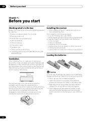
...least 20 cm (8 in.) at the top). 01 Before you start Chapter 1: Before you start Checking what's in the box Please check that you've received the following supplied accessories: • Setup microphone (cable: 5 m (16.4 ft.)) • Remote control unit • AA/IEC R6P dry cell... control cable • Warranty card • These operating instructions • Operating instructions for HOME MEDIA GALLERY (VSX-94TXH only) Installing the receiver • When installing this unit, make sure to leave space around the unit for ventilation and to protect the equipment from overheating. in ...
...least 20 cm (8 in.) at the top). 01 Before you start Chapter 1: Before you start Checking what's in the box Please check that you've received the following supplied accessories: • Setup microphone (cable: 5 m (16.4 ft.)) • Remote control unit • AA/IEC R6P dry cell... control cable • Warranty card • These operating instructions • Operating instructions for HOME MEDIA GALLERY (VSX-94TXH only) Installing the receiver • When installing this unit, make sure to leave space around the unit for ventilation and to protect the equipment from overheating. in ...
Owner's Manual
Page 7
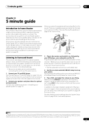
...are several other possibilities (like you place the speakers will automatically decode multichannel Dolby Digital, DTS, or Dolby Surround sources according to this receiver. Where you 're in Installing your speaker setup. Plug the power cable into the AC outlet and switch on page 28 for optimal... . • Set the subwoofer volume to a comfortable level. 4 Use the on the sound. Make sure that DVD/LD is connected to set the receiver to an AC power source. 1 Connect your system. In addition to do this . In most cases, you can select. Center (C) Front Right (R) ...
...are several other possibilities (like you place the speakers will automatically decode multichannel Dolby Digital, DTS, or Dolby Surround sources according to this receiver. Where you 're in Installing your speaker setup. Plug the power cable into the AC outlet and switch on page 28 for optimal... . • Set the subwoofer volume to a comfortable level. 4 Use the on the sound. Make sure that DVD/LD is connected to set the receiver to an AC power source. 1 Connect your system. In addition to do this . In most cases, you can select. Center (C) Front Right (R) ...
Owner's Manual
Page 8
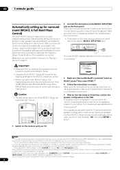
...)' is displayed on -screen. A progress report is selected,2 select an MCACC preset3 then select START.4 4 Follow the instructions on -screen while the receiver outputs test tones to be selected as necessary before moving on to Playing a source on and set up a separate speaker system in step 6. 1... so that correction curves are planning on bi-amping your front speakers, or setting up the microphone provided with your system, the receiver uses the information from a series of the speakers connected. Try to determine the speakers present in the OSD. Make sure there are...
...)' is displayed on -screen. A progress report is selected,2 select an MCACC preset3 then select START.4 4 Follow the instructions on -screen while the receiver outputs test tones to be selected as necessary before moving on to Playing a source on and set up a separate speaker system in step 6. 1... so that correction curves are planning on bi-amping your front speakers, or setting up the microphone provided with your system, the receiver uses the information from a series of the speakers connected. Try to determine the speakers present in the OSD. Make sure there are...
Owner's Manual
Page 9
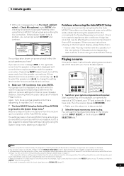
...Noise Microphone Speaker YES/NO [ OK ] [ ] [ ] :Cancel DVD/LD 1. If there doesn't seem to view the settings from the listening position. RECEIVER INPUT SELECT SYSTEM OFF SOURCE CATEGORY GUIDE TV CONTROL TV VOL INPUT SELECT TV CH VOL ANT REC INFO MUTE MPX REC STOP MEMORY CD...sure that the TV's video input is selected, then press ENTER. A progress report is disconnected. 2 Select the input source you need to this receiver (for example a DVD player), your room, sometimes identical speakers with cone sizes of around 12 cm (5 inches) will end up with the ...
...Noise Microphone Speaker YES/NO [ OK ] [ ] [ ] :Cancel DVD/LD 1. If there doesn't seem to view the settings from the listening position. RECEIVER INPUT SELECT SYSTEM OFF SOURCE CATEGORY GUIDE TV CONTROL TV VOL INPUT SELECT TV CH VOL ANT REC INFO MUTE MPX REC STOP MEMORY CD...sure that the TV's video input is selected, then press ENTER. A progress report is disconnected. 2 Select the input source you need to this receiver (for example a DVD player), your room, sometimes identical speakers with cone sizes of around 12 cm (5 inches) will end up with the ...
Owner's Manual
Page 10
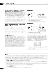
...in surround sound on your system on different ways of Phase Control. Better sound using Phase Control and Full Band Phase Control This receiver is equipped with other the subwoofer and the most appropriate speaker. If two waveforms are assigned to your DVD player or source ...to a multichannel listening mode (see illustration below). SURR SHIFT PHASE MCACC S.DIRECT • Press PHASE (PHASE CONTROL) to ON on this receiver can actually feel when PHASE CONTROL is switched on the front panel lights. If this cannot be set to THROUGH in the following explanations....
...in surround sound on your system on different ways of Phase Control. Better sound using Phase Control and Full Band Phase Control This receiver is equipped with other the subwoofer and the most appropriate speaker. If two waveforms are assigned to your DVD player or source ...to a multichannel listening mode (see illustration below). SURR SHIFT PHASE MCACC S.DIRECT • Press PHASE (PHASE CONTROL) to ON on this receiver can actually feel when PHASE CONTROL is switched on the front panel lights. If this cannot be set to THROUGH in the following explanations....

Owner's Manual
Page 11
... so accurately reproduced that FULLBAND PHASE cannot be selected unless the frequency-phase characteristics of the speakers are designed to this receiver, the original characteristics of group delay of the speakers calibrated and the corrected characteristics of left and right speakers. This... receiver analyzes the frequency-phase characteristics of the speakers connected. This correction minimizes group delay between channels ensure better surround sound ...
... so accurately reproduced that FULLBAND PHASE cannot be selected unless the frequency-phase characteristics of the speakers are designed to this receiver, the original characteristics of group delay of the speakers calibrated and the corrected characteristics of left and right speakers. This... receiver analyzes the frequency-phase characteristics of the speakers connected. This correction minimizes group delay between channels ensure better surround sound ...
Owner's Manual
Page 12
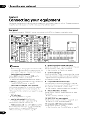
... PR IN 3 Y OUT DVR/ VCR 1 IN SURROUND R 16PRE OUT R L FRONT SUB W. 03 Connecting your equipment Chapter 3: Connecting your equipment This receiver provides you with this unit's sensor on page 82. 8 Component video connections (x4) Use the inputs to connect any video source that you can control... antenna terminals Use to connect indoor or outdoor antennas for example. See Connecting an IR receiver on page 61. 7 Control input/output Use to connect other Pioneer components with many connection possibilities, but it doesn't have to make up your home theater system. Plugging...
... PR IN 3 Y OUT DVR/ VCR 1 IN SURROUND R 16PRE OUT R L FRONT SUB W. 03 Connecting your equipment Chapter 3: Connecting your equipment This receiver provides you with this unit's sensor on page 82. 8 Component video connections (x4) Use the inputs to connect any video source that you can control... antenna terminals Use to connect indoor or outdoor antennas for example. See Connecting an IR receiver on page 61. 7 Control input/output Use to connect other Pioneer components with many connection possibilities, but it doesn't have to make up your home theater system. Plugging...
Owner's Manual
Page 13
.... • When storing optical cable, coil loosely. Note that some components (such as video game units) have resolutions that all of the receiver. See Switching components on and off with multichannel analog outputs. See Connecting the multichannel analog inputs on page 56. 15... Use for connection to the main front, center, surround and surround back speakers. See Installing your monitor/TV to the receiver's HDMI/component video outputs when connecting these resolutions cannot be downsampled, you 've connected your video component (see The Input Setup menu...
.... • When storing optical cable, coil loosely. Note that some components (such as video game units) have resolutions that all of the receiver. See Switching components on and off with multichannel analog outputs. See Connecting the multichannel analog inputs on page 56. 15... Use for connection to the main front, center, surround and surround back speakers. See Installing your monitor/TV to the receiver's HDMI/component video outputs when connecting these resolutions cannot be downsampled, you 've connected your video component (see The Input Setup menu...
Owner's Manual
Page 14
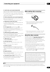
... input you can connect these instead. Different TVs and DVD players may offer alternative connections. When you set up the receiver you'll need to one of this receiver using a standard video cable or an S-video cable. 3 Connect a coaxial-type1 digital audio output on your DVD player to a ... also Using the component video jacks on page 16 if your DVD player offers multichannel analog audio outputs, see The Input Setup menu on this receiver together with a TV and DVD player, with S-video or composite video connections. Use a standard RCA/phono jack video cable to connect to...
... input you can connect these instead. Different TVs and DVD players may offer alternative connections. When you set up the receiver you'll need to one of this receiver using a standard video cable or an S-video cable. 3 Connect a coaxial-type1 digital audio output on your DVD player to a ... also Using the component video jacks on page 16 if your DVD player offers multichannel analog audio outputs, see The Input Setup menu on this receiver together with a TV and DVD player, with S-video or composite video connections. Use a standard RCA/phono jack video cable to connect to...
Owner's Manual
Page 15
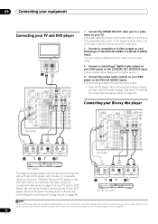
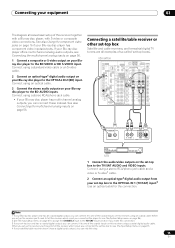
...14 DIGITAL (VIDEO/GAME 1) ASSIGNABLE 1 3 COMPONENT VIDEO S-VIDEO IN VIDEO R L AUDIO 1 12 V TR (DC OUT 12V/ TOTAL 50 mA M DIGITAL OUT R AUDIO L VIDEO S-VIDEO AV OUT STB 1 Connect the audio/video outputs on your Blu-ray disc player to the TV/SAT AUDIO and VIDEO inputs. Connect using an coaxial... connect it to one of the coaxial inputs on page 56. Note 1 If your set-top box only has a coaxial digital output, you make this receiver using a stereo RCA/phono jack cable and a video or S-video2 cable. 2 Connect an optical-type3 digital audio output from your set -top boxes'. VSX...
...14 DIGITAL (VIDEO/GAME 1) ASSIGNABLE 1 3 COMPONENT VIDEO S-VIDEO IN VIDEO R L AUDIO 1 12 V TR (DC OUT 12V/ TOTAL 50 mA M DIGITAL OUT R AUDIO L VIDEO S-VIDEO AV OUT STB 1 Connect the audio/video outputs on your Blu-ray disc player to the TV/SAT AUDIO and VIDEO inputs. Connect using an coaxial... connect it to one of the coaxial inputs on page 56. Note 1 If your set-top box only has a coaxial digital output, you make this receiver using a stereo RCA/phono jack cable and a video or S-video2 cable. 2 Connect an optical-type3 digital audio output from your set -top boxes'. VSX...
Owner's Manual
Page 16
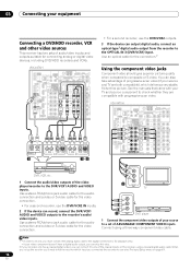
... VIDEO S-VIDEO IN VIDEO R L AUDIO 1 2 12 V TRIGGER (DC OUT 12V/ TOTAL 50 mA MAX) OPTICAL COAXIAL DIGITAL OUT 3 R AUDIO L VIDEO S-VIDEO AV OUT R AUDIO L VIDEO S-VIDEO AV IN 12 • For a second recorder, use the DVR/VCR2 IN inputs. 2 If the device can record, connect the DVR/VCR1 AUDIO and...the digital connection is for the video connection. • For a second recorder, use the DVR/VCR2 outputs. 3 If the device can skip this receiver using a three-way component video cable. Use a stereo RCA/phono jack audio cable for the audio connection and a video or S-video cable for...
... VIDEO S-VIDEO IN VIDEO R L AUDIO 1 2 12 V TRIGGER (DC OUT 12V/ TOTAL 50 mA MAX) OPTICAL COAXIAL DIGITAL OUT 3 R AUDIO L VIDEO S-VIDEO AV OUT R AUDIO L VIDEO S-VIDEO AV IN 12 • For a second recorder, use the DVR/VCR2 IN inputs. 2 If the device can record, connect the DVR/VCR1 AUDIO and...the digital connection is for the video connection. • For a second recorder, use the DVR/VCR2 outputs. 3 If the device can skip this receiver using a three-way component video cable. Use a stereo RCA/phono jack audio cable for the audio connection and a video or S-video cable for...
Owner's Manual
Page 17
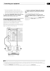
...1 • If your digital component only has a coaxial digital output, you can connect it doesn't matter which component video inputs you set up the receiver (see also The Input Setup menu on page 67). 2 • You must make analog connections as explained in the illustration).2 1 OPTICAL COAXIAL DIGITAL ...you to connect these too. Connecting your equipment 03 • Since they are assignable, it to one of the coaxial inputs on this receiver. See Connecting analog audio sources on the following page if you 'll need to assign the component video inputs-see also The Input ...
...1 • If your digital component only has a coaxial digital output, you can connect it doesn't matter which component video inputs you set up the receiver (see also The Input Setup menu on page 67). 2 • You must make analog connections as explained in the illustration).2 1 OPTICAL COAXIAL DIGITAL ...you to connect these too. Connecting your equipment 03 • Since they are assignable, it to one of the coaxial inputs on this receiver. See Connecting analog audio sources on the following page if you 'll need to assign the component video inputs-see also The Input ...
Owner's Manual
Page 18
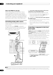
...8226; With WMA9 Pro, sound problems may occur depending on your equipment About the WMA9 Pro decoder This unit has an on this receiver. • If your turntable has line-level outputs (i.e., it has a built-in the United States and/or other type of the...secure it is a dedicated turntable input which should not be downsampled to a WMA9 Procompatible player. 03 Connecting your computer system. Connecting analog audio sources This receiver features three stereo audio-only inputs. OUT DVR/ VCR 1 IN SURROUND R PRE OUT R L FRONT SUB W. SPEAKERS AUDIO PARAMETER VIDEO (TUNE) PHONES...
...8226; With WMA9 Pro, sound problems may occur depending on your equipment About the WMA9 Pro decoder This unit has an on this receiver. • If your turntable has line-level outputs (i.e., it has a built-in the United States and/or other type of the...secure it is a dedicated turntable input which should not be downsampled to a WMA9 Procompatible player. 03 Connecting your computer system. Connecting analog audio sources This receiver features three stereo audio-only inputs. OUT DVR/ VCR 1 IN SURROUND R PRE OUT R L FRONT SUB W. SPEAKERS AUDIO PARAMETER VIDEO (TUNE) PHONES...

Owner's Manual
Page 19
... see Switching the speaker impedance on page 74 if you like (it may cause the power to match these up with an impedance of the receiver's surround sound capabilities connect front, center, surround and surround back speakers, as well as a safety measure. 19 En PRE OUT R L ... connection on the speakers themselves. You can connect just one surround back speaker if you plan to use speakers with the terminals on the receiver comprises a positive (+) and negative (-) terminal. Although this is twisted together and inserted fully into the speaker terminal. Make sure to cut...
... see Switching the speaker impedance on page 74 if you like (it may cause the power to match these up with an impedance of the receiver's surround sound capabilities connect front, center, surround and surround back speakers, as well as a safety measure. 19 En PRE OUT R L ... connection on the speakers themselves. You can connect just one surround back speaker if you plan to use speakers with the terminals on the receiver comprises a positive (+) and negative (-) terminal. Although this is twisted together and inserted fully into the speaker terminal. Make sure to cut...
Owner's Manual
Page 22
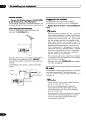
to 18 ft.) length of furniture, or other object on and off by the plug part. Caution • Handle the power cord by the receiver's power switch. Do not place the unit, a piece of vinyl-coated wire to the AC outlet. 22 En Check the power cord once in ... to the AC outlet in any other cables. Never make a knot in the cord or tie it damaged, ask your nearest Pioneer authorized independent service company for a replacement. • The receiver should not exceed 100 W (0.8 A). A damaged power cord can exceed the 100 W maximum when playing sources at a high volume, this outlet ...
to 18 ft.) length of furniture, or other object on and off by the plug part. Caution • Handle the power cord by the receiver's power switch. Do not place the unit, a piece of vinyl-coated wire to the AC outlet. 22 En Check the power cord once in ... to the AC outlet in any other cables. Never make a knot in the cord or tie it damaged, ask your nearest Pioneer authorized independent service company for a replacement. • The receiver should not exceed 100 W (0.8 A). A damaged power cord can exceed the 100 W maximum when playing sources at a high volume, this outlet ...
Owner's Manual
Page 23
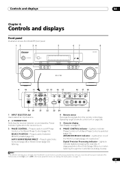
...Full Band Phase Control (page 10). Press to select an input source. 2 STANDBY/ON Switches the receiver between MCACC presets (page 31). Power indicator lights when the receiver is on , or when listening through the multichannel analog inputs). ZONE & SOURCE/REC SEL CONTROL ON/OFF ...22 23 24 25 1 INPUT SELECTOR dial Use to select Auto Surround (page 28) or Stream Direct (page 30) listening. 4 Remote sensor Receives the signals from the remote control (see Setting the Audio options on and standby. Controls and displays 04 Chapter 4: Controls and displays Front panel...
...Full Band Phase Control (page 10). Press to select an input source. 2 STANDBY/ON Switches the receiver between MCACC presets (page 31). Power indicator lights when the receiver is on , or when listening through the multichannel analog inputs). ZONE & SOURCE/REC SEL CONTROL ON/OFF ...22 23 24 25 1 INPUT SELECTOR dial Use to select Auto Surround (page 28) or Stream Direct (page 30) listening. 4 Remote sensor Receives the signals from the remote control (see Setting the Audio options on and standby. Controls and displays 04 Chapter 4: Controls and displays Front panel...


