
Owners Manual
Page 2
... 2 WARNING 2 Setting the Unit 3 Bass Boost Frequency Control 3 Gain Control 3 MODE SELECT Switch 3 Bass Boost Level Control 3 Cut Off Frequency Control for LPF 4 Subsonic Select Switch 4 BFC (Beat Frequency Control) Switch 4 Power Indicator 4 Connecting the Unit 5 Connection Diagram 6 Connecting the Power Terminal 7 Connecting the Speaker Terminals 8 Setting the Gain for Synced Amplifier 9 Quick Setup of the Gain 9 Advanced Setup of the Gain 9 Connecting the Speaker Wires 9 Installation 13 Example of installation on the floor mat or on the chassis 13 Specifications 14 1
... 2 WARNING 2 Setting the Unit 3 Bass Boost Frequency Control 3 Gain Control 3 MODE SELECT Switch 3 Bass Boost Level Control 3 Cut Off Frequency Control for LPF 4 Subsonic Select Switch 4 BFC (Beat Frequency Control) Switch 4 Power Indicator 4 Connecting the Unit 5 Connection Diagram 6 Connecting the Power Terminal 7 Connecting the Speaker Terminals 8 Setting the Gain for Synced Amplifier 9 Quick Setup of the Gain 9 Advanced Setup of the Gain 9 Connecting the Speaker Wires 9 Installation 13 Example of installation on the floor mat or on the chassis 13 Specifications 14 1
Owners Manual
Page 3
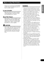
... sold battery wire blows. Before attempting operation, be sure to the amplifier (sound will cut the power supply to disconnect the negative (-) terminal of the battery beforehand. • Confirm that you can still hear normal traffic sound. • Check the connections of any attached speakers could result. WARNING • Always use the recommended battery wire and ground wire, which is a mono amplifier. In such a case, switch the power to read this PIONEER...
... sold battery wire blows. Before attempting operation, be sure to the amplifier (sound will cut the power supply to disconnect the negative (-) terminal of the battery beforehand. • Confirm that you can still hear normal traffic sound. • Check the connections of any attached speakers could result. WARNING • Always use the recommended battery wire and ground wire, which is a mono amplifier. In such a case, switch the power to read this PIONEER...
Owners Manual
Page 4
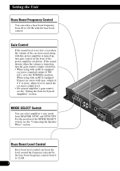
... this power amplifier is turned up, turn gain control on the front of 4 V or more, adjust level to match the car stereo output level. • For synced amplifier's gain control, see the "Connecting the Speaker Wires" section. Gain Control If the sound level is too low, even when the volume of the car stereo used along with an RCA equipped car stereo (standard output of the MODE SELECT switch, see the "Setting the Gain for Synced Amplifier" section. Bass Boost Level Control Bass boost level control can boost the level around the frequency selected by the bass boost frequency control...
... this power amplifier is turned up, turn gain control on the front of 4 V or more, adjust level to match the car stereo output level. • For synced amplifier's gain control, see the "Connecting the Speaker Wires" section. Gain Control If the sound level is too low, even when the volume of the car stereo used along with an RCA equipped car stereo (standard output of the MODE SELECT switch, see the "Setting the Gain for Synced Amplifier" section. Bass Boost Level Control Bass boost level control can boost the level around the frequency selected by the bass boost frequency control...

Owners Manual
Page 5
Subsonic Select Switch The subsonic filter cuts inaudible frequencies below 20 Hz to 240 Hz. ESPAÑOL DEUTSCH FRANÇAIS ITALIANO NEDERLANDS Power Indicator The power indicator lights when the power is switched on. ENGLISH Cut Off Frequency Control for LPF You can select a cut off frequency from 40 to eliminate unwanted vibrations and minimize power loss. 4 BFC (Beat Frequency Control) Switch If you hear a beat while listening to an MW/LW broadcast with your car stereo, change the BFC switch using a small standard tip screwdriver.
Subsonic Select Switch The subsonic filter cuts inaudible frequencies below 20 Hz to 240 Hz. ESPAÑOL DEUTSCH FRANÇAIS ITALIANO NEDERLANDS Power Indicator The power indicator lights when the power is switched on. ENGLISH Cut Off Frequency Control for LPF You can select a cut off frequency from 40 to eliminate unwanted vibrations and minimize power loss. 4 BFC (Beat Frequency Control) Switch If you hear a beat while listening to an MW/LW broadcast with your car stereo, change the BFC switch using a small standard tip screwdriver.
Owners Manual
Page 6
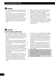
... NOT connect a subwoofer with a 12-volt battery and negative grounding. regardless of whether the car stereo is on for vehicles with a lower impedance than the original fuse. Amplifier damage, smoke, and overheating could result from the antenna, antenna cable and tuner. • Cords for this , the battery could also become damaged. • Install and route the separately sold battery wire, ground wire, speaker wires and the amplifier as...
... NOT connect a subwoofer with a 12-volt battery and negative grounding. regardless of whether the car stereo is on for vehicles with a lower impedance than the original fuse. Amplifier damage, smoke, and overheating could result from the antenna, antenna cable and tuner. • Cords for this , the battery could also become damaged. • Install and route the separately sold battery wire, ground wire, speaker wires and the amplifier as...
Owners Manual
Page 7
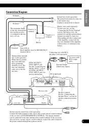
... SEPARATELY fused at the amplifier, connect the battery wire terminal of the amplifier to the positive (+) terminal of the car stereo (SYSTEM REMOTE CONTROL). The wire size should be same size as the battery wire. Connect to the auto-antenna relay control terminal. Optional direct ground wire (sold separately) For the wire size, see the "Connecting the Power Terminal" section. SYNC OUTPUT / SYNC INPUT jack See the "Connecting the Speaker Wires" section for speaker connection instructions. Connecting wire with RCA output jacks External Output (Subwoofer output) RCA input...
... SEPARATELY fused at the amplifier, connect the battery wire terminal of the amplifier to the positive (+) terminal of the car stereo (SYSTEM REMOTE CONTROL). The wire size should be same size as the battery wire. Connect to the auto-antenna relay control terminal. Optional direct ground wire (sold separately) For the wire size, see the "Connecting the Power Terminal" section. SYNC OUTPUT / SYNC INPUT jack See the "Connecting the Speaker Wires" section for speaker connection instructions. Connecting wire with RCA output jacks External Output (Subwoofer output) RCA input...
Owners Manual
Page 8
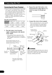
... terminal System remote control wire Ground wire Terminal screw Power terminal Battery wire WARNING Failure to securely fasten the battery wire to overheat and could result in damage and injury including minor burns. After connecting the wires to the car body. • Recommended wires size (AWG: American Wire Gauge) is 45 cm. Connect the battery wire directly to the car battery positive terminal (+) and the ground wire to the terminals, attach the endcap. • Fix the wires securely with the terminal screws. Connecting the Unit Connecting the Power Terminal...
... terminal System remote control wire Ground wire Terminal screw Power terminal Battery wire WARNING Failure to securely fasten the battery wire to overheat and could result in damage and injury including minor burns. After connecting the wires to the car body. • Recommended wires size (AWG: American Wire Gauge) is 45 cm. Connect the battery wire directly to the car battery positive terminal (+) and the ground wire to the terminals, attach the endcap. • Fix the wires securely with the terminal screws. Connecting the Unit Connecting the Power Terminal...
Owners Manual
Page 9
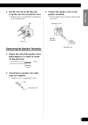
Slit 3. Attach lugs to the speaker terminals. • Fix the speaker wires securely with the terminal screws. Connect the speaker wires to speaker wire ends. Lug Speaker wire Speaker terminal Speaker wire FRANÇAIS ITALIANO NEDERLANDS 8 ENGLISH ESPAÑOL DEUTSCH 4. Lugs not supplied. • Use pliers, etc., to crimp lugs to wires. Terminal screw Wire tie Connecting the Speaker Terminals 1. Expose the end of the speaker wires using nippers or a cutter by about 10 mm and twist. Twist...
Slit 3. Attach lugs to the speaker terminals. • Fix the speaker wires securely with the terminal screws. Connect the speaker wires to speaker wire ends. Lug Speaker wire Speaker terminal Speaker wire FRANÇAIS ITALIANO NEDERLANDS 8 ENGLISH ESPAÑOL DEUTSCH 4. Lugs not supplied. • Use pliers, etc., to crimp lugs to wires. Terminal screw Wire tie Connecting the Speaker Terminals 1. Expose the end of the speaker wires using nippers or a cutter by about 10 mm and twist. Twist...
Owners Manual
Page 10
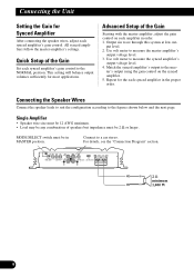
... master amplifier, adjust the gain control on the synced amplifier. 5. Use volt meter to the NORMAL position. ter's output using the gain control on each synced amplifier's gain control to measure the master amplifier's output voltage level. 3. Quick Setup of speakers but impedance must be 2 Ω or larger. Connect to the mas- Match the synced amplifier's output to a car stereo. Output sin wave through this system at low out- Repeat for most applications. MODE SELECT switch...
... master amplifier, adjust the gain control on the synced amplifier. 5. Use volt meter to the NORMAL position. ter's output using the gain control on each synced amplifier's gain control to measure the master amplifier's output voltage level. 3. Quick Setup of speakers but impedance must be 2 Ω or larger. Connect to the mas- Match the synced amplifier's output to a car stereo. Output sin wave through this system at low out- Repeat for most applications. MODE SELECT switch...
Owners Manual
Page 11
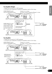
..., see the "Connection Diagram" section. ENGLISH ESPAÑOL DEUTSCH Two Amplifier Bridged • Speaker wire size must be 12 AWG minimum. • Load may be any combination of speakers but impedance must be 4 Ω or larger. Connect to a car stereo. Before setting to the position, remove the screw and the stopper. MODE SELECT switch must be in SYNC INV position. Connecting wire with RCA pin plugs (sold separately...
..., see the "Connection Diagram" section. ENGLISH ESPAÑOL DEUTSCH Two Amplifier Bridged • Speaker wire size must be 12 AWG minimum. • Load may be any combination of speakers but impedance must be 4 Ω or larger. Connect to a car stereo. Before setting to the position, remove the screw and the stopper. MODE SELECT switch must be in SYNC INV position. Connecting wire with RCA pin plugs (sold separately...
Owners Manual
Page 12
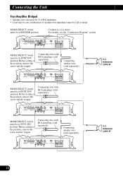
...). MODE SELECT switch must be in MASTER position. MODE SELECT switch must be in SYNC INV position. Before setting to a car stereo. MODE SELECT switch must be 4 Ω or larger. Connecting wire with RCA pin plugs (sold separately). Connecting wire with RCA pin plugs (sold separately). 4 Ω minimum 2,000 W 4 Ω minimum 2,000 W 11 Connect to the position, remove the screw and the stopper. Connecting speaker wire (sold separately). Connecting the Unit Four Amplifier Bridged • Speaker wire size must...
...). MODE SELECT switch must be in MASTER position. MODE SELECT switch must be in SYNC INV position. Before setting to a car stereo. MODE SELECT switch must be 4 Ω or larger. Connecting wire with RCA pin plugs (sold separately). Connecting wire with RCA pin plugs (sold separately). 4 Ω minimum 2,000 W 4 Ω minimum 2,000 W 11 Connect to the position, remove the screw and the stopper. Connecting speaker wire (sold separately). Connecting the Unit Four Amplifier Bridged • Speaker wire size must...
Owners Manual
Page 13
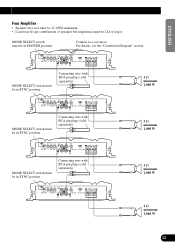
...ÑOL DEUTSCH Four Amplifier • Speaker wire size must be 12 AWG minimum. • Load may be any combination of speakers but impedance must be in SYNC position. MODE SELECT switch must be in SYNC position. Connecting wire with RCA pin plugs (sold separately). 2 Ω minimum 1,000 W FRANÇAIS ITALIANO NEDERLANDS 2 Ω minimum 1,000 W 12 MODE SELECT switch must be 2 Ω...
...ÑOL DEUTSCH Four Amplifier • Speaker wire size must be 12 AWG minimum. • Load may be any combination of speakers but impedance must be in SYNC position. MODE SELECT switch must be in SYNC position. Connecting wire with RCA pin plugs (sold separately). 2 Ω minimum 1,000 W FRANÇAIS ITALIANO NEDERLANDS 2 Ω minimum 1,000 W 12 MODE SELECT switch must be 2 Ω...
Owners Manual
Page 14
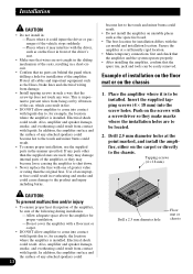
...; DO NOT allow amplifier to come into the screw holes. Use of an improper fuse could result in overheating and smoke and could result from being cut by vibration of the car, which can be installed. Example of installation on the floor mat or on the floor in front of the driver's seat. • Make sure that wires are not caught...
...; DO NOT allow amplifier to come into the screw holes. Use of an improper fuse could result in overheating and smoke and could result from being cut by vibration of the car, which can be installed. Example of installation on the floor mat or on the floor in front of the driver's seat. • Make sure that wires are not caught...
Owners Manual
Page 15
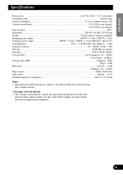
... this unit when an audio signal is input. Bridge 4 - 16 Ω) Frequency response ...10 - 240 Hz (+0 dB, -1 dB) S/N ratio ...90 dB (IEC-A network) Distortion ...0.05 % (50 W, 100 Hz) Low pass filter ...Cut off frequency: 40 - 240 Hz Cut off slope: -24 dB/oct Subsonic filter (HPF) ...Frequency: 20 Hz Slope: -18 dB Bass boost ...Level: 0 - 12 dB Frequency: 40 - 120 Hz Phase control ...SYNC, SYNC INV Gain control...
... this unit when an audio signal is input. Bridge 4 - 16 Ω) Frequency response ...10 - 240 Hz (+0 dB, -1 dB) S/N ratio ...90 dB (IEC-A network) Distortion ...0.05 % (50 W, 100 Hz) Low pass filter ...Cut off frequency: 40 - 240 Hz Cut off slope: -24 dB/oct Subsonic filter (HPF) ...Frequency: 20 Hz Slope: -18 dB Bass boost ...Level: 0 - 12 dB Frequency: 40 - 120 Hz Phase control ...SYNC, SYNC INV Gain control...
Owners Manual
Page 86
... Chapultepec, Mexico, D.F. 11000 TEL: 55-9178-4270 Published by Pioneer Corporation. Copyright © 2004 Pioneer Corporation. Copyright © 2004 by Pioneer Corporation. Imprimé aux Etats-Unis EW Printed in U.S.A. P.O. Publication de Pioneer Corporation. de C.V. PIONEER CORPORATION 4-1, MEGURO 1-CHOME, MEGURO-KU, TOKYO 153-8654, JAPAN PIONEER ELECTRONICS (USA) INC. Tous droits de reproduction et de traduction...
... Chapultepec, Mexico, D.F. 11000 TEL: 55-9178-4270 Published by Pioneer Corporation. Copyright © 2004 Pioneer Corporation. Copyright © 2004 by Pioneer Corporation. Imprimé aux Etats-Unis EW Printed in U.S.A. P.O. Publication de Pioneer Corporation. de C.V. PIONEER CORPORATION 4-1, MEGURO 1-CHOME, MEGURO-KU, TOKYO 153-8654, JAPAN PIONEER ELECTRONICS (USA) INC. Tous droits de reproduction et de traduction...


