
Owner's Manual
Page 5
...How to Use This Manual 2 Checking Supplied Accessories 3 Part Names and Functions 4 Main Unit 4 Remote Control Unit 5 Connection Panel 6 Installation and Connections 8 Installation of Terms 42 1 PRO-1000HDI / PRO-800HDI Always have an installation specialist or your Plasma Display, please carefully read the "Safety Precautions" ...Cord Connection 16 How to operate the Plasma Display properly. Before using your dealer install and set up the product. PIONEER cannot assume liabilities for Dealers: After installation, be sure to deliver this manual in a safe place. Keep this...
...How to Use This Manual 2 Checking Supplied Accessories 3 Part Names and Functions 4 Main Unit 4 Remote Control Unit 5 Connection Panel 6 Installation and Connections 8 Installation of Terms 42 1 PRO-1000HDI / PRO-800HDI Always have an installation specialist or your Plasma Display, please carefully read the "Safety Precautions" ...Cord Connection 16 How to operate the Plasma Display properly. Before using your dealer install and set up the product. PIONEER cannot assume liabilities for Dealers: After installation, be sure to deliver this manual in a safe place. Keep this...
Owner's Manual
Page 6
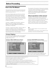
... display and connected components. Screen Displays The example screen displays provided in both the PRO-1000HDI and PRO-800HDI. The PRO-800HDI display differs as shown: Example of PRO-1000HDI Screen Display: ÷ The PRO-1000HDI screen display has a nondisplaying border at each side of Microsoft Corporation. MAIN MENU ... order that would seem most logical for someone setting up to the more complex operations associated with the plasma monitor and remote control unit, as their respective buttons and controls will be referred to throughout this manual. The remainder of the sections ...
... display and connected components. Screen Displays The example screen displays provided in both the PRO-1000HDI and PRO-800HDI. The PRO-800HDI display differs as shown: Example of PRO-1000HDI Screen Display: ÷ The PRO-1000HDI screen display has a nondisplaying border at each side of Microsoft Corporation. MAIN MENU ... order that would seem most logical for someone setting up to the more complex operations associated with the plasma monitor and remote control unit, as their respective buttons and controls will be referred to throughout this manual. The remainder of the sections ...
Owner's Manual
Page 7
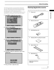
...CONT RAST BR I ON : 0 ADJUST MENU SET EXIT SET 5 Press 5/∞/2/3 to adjust the value. ÷ Operating Instructions ÷ Warranty 3 PRO-1000HDI / PRO-800HDI ENHANCE :0 :0 : +60 : +60 : +60 :0 :0 SET UP INPUT1 OPTION RE S ET SELECT SET ENTER MENU EXIT 2 Press ... wiping front panel) 5 Speed clamps (x 2) 6 Bead bands (x 2) H. Before Proceeding Before Proceeding The following accessories were supplied. 1 Power cord 2 Remote control unit 3 AA (R6) batteries (x 2) SELECT SET ENTER MENU EXIT 3 Press 5/∞ to select the item to be adjusted. MAIN MENU PICTURE...
...CONT RAST BR I ON : 0 ADJUST MENU SET EXIT SET 5 Press 5/∞/2/3 to adjust the value. ÷ Operating Instructions ÷ Warranty 3 PRO-1000HDI / PRO-800HDI ENHANCE :0 :0 : +60 : +60 : +60 :0 :0 SET UP INPUT1 OPTION RE S ET SELECT SET ENTER MENU EXIT 2 Press ... wiping front panel) 5 Speed clamps (x 2) 6 Bead bands (x 2) H. Before Proceeding Before Proceeding The following accessories were supplied. 1 Power cord 2 Remote control unit 3 AA (R6) batteries (x 2) SELECT SET ENTER MENU EXIT 3 Press 5/∞ to select the item to be adjusted. MAIN MENU PICTURE...

Owner's Manual
Page 8
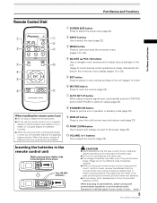
...-screen menu (pages 18 to 34). 6 ADJUST (5/∞/3/2) buttons Use to navigate menu screens and to optimum values (page 28). 4 PRO-1000HDI / PRO-800HDI The flashing pattern is also used to indicate error messages (page 37). 2 Remote control sensor Point the remote control toward the remote sensor to green when the unit is operating (page 26).
...-screen menu (pages 18 to 34). 6 ADJUST (5/∞/3/2) buttons Use to navigate menu screens and to optimum values (page 28). 4 PRO-1000HDI / PRO-800HDI The flashing pattern is also used to indicate error messages (page 37). 2 Remote control sensor Point the remote control toward the remote sensor to green when the unit is operating (page 26).
Owner's Manual
Page 9
...optimum values (page 28). 8 STANDBY/ON button Press to put the unit in a place subject to excessive humidity. ¶ When the remote control unit's batteries begin to adjust or enter various settings on the unit. Usage of cursor buttons within operations is removed, and then insert...disassemble or throw the provided batteries in a location subject to direct sunlight, heat radiation from the remote control unit to select and enlarge one part of battery fluid. H048 En 5 PRO-1000HDI / PRO-800HDI If battery liquid has leaked, thoroughly wipe the inside of the case until all batteries ...
...optimum values (page 28). 8 STANDBY/ON button Press to put the unit in a place subject to excessive humidity. ¶ When the remote control unit's batteries begin to adjust or enter various settings on the unit. Usage of cursor buttons within operations is removed, and then insert...disassemble or throw the provided batteries in a location subject to direct sunlight, heat radiation from the remote control unit to select and enlarge one part of battery fluid. H048 En 5 PRO-1000HDI / PRO-800HDI If battery liquid has leaked, thoroughly wipe the inside of the case until all batteries ...
Owner's Manual
Page 10
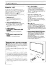
... set this switch to an external monitor or other component that the connection made at the remote sensor (Î) located on the installation surroundings, this switch to PIONEER components bearing the Î mark. If you are having difficulty with four video input terminals ... Panel The connection panel is operable up to the picture displayed. 6 PRO-1000HDI / PRO-800HDI 7 m (23 feet) 30˚ 30˚ Remote Sensor Should this unit. ¶ Depending on the front panel of PIONEER components that the connection made corresponds to 12). 8 Synchronizing signal impedance selector...
... set this switch to an external monitor or other component that the connection made at the remote sensor (Î) located on the installation surroundings, this switch to PIONEER components bearing the Î mark. If you are having difficulty with four video input terminals ... Panel The connection panel is operable up to the picture displayed. 6 PRO-1000HDI / PRO-800HDI 7 m (23 feet) 30˚ 30˚ Remote Sensor Should this unit. ¶ Depending on the front panel of PIONEER components that the connection made corresponds to 12). 8 Synchronizing signal impedance selector...

Owner's Manual
Page 20
...converter plug, use a power supply voltage other than that component will no resistance). 16 PRO-1000HDI / PRO-800HDI When the connection is made , remote control operation of the connected component at the remote control sensor on this may cause fire or electric shock. ÷ For the plasma ...the power cord into a power outlet. Always be sure to connect the power cord to control. Point the remote control unit of connected PIONEER components that the cord is properly grounded. Installation and Connections Control Cord Connection When control cord connections are monaural ...
...converter plug, use a power supply voltage other than that component will no resistance). 16 PRO-1000HDI / PRO-800HDI When the connection is made , remote control operation of the connected component at the remote control sensor on this may cause fire or electric shock. ÷ For the plasma ...the power cord into a power outlet. Always be sure to connect the power cord to control. Point the remote control unit of connected PIONEER components that the cord is properly grounded. Installation and Connections Control Cord Connection When control cord connections are monaural ...

Owner's Manual
Page 26
... to INPUT1 and INPUT2 as described in the section "Setting Up the System" on page 18. The STANDBY/ON indicator turns green. 22 PRO-1000HDI / PRO-800HDI FULL 4 Use VOLUME +/- Doing so may continue to select connected components. Operations Selecting an Input Source This section explains the basic operation...is not necessary. 3 Press INPUT on position to select the input. Main Unit Operating Panel 4 Remote Control Unit 1 Switch the main power switch on the main unit to the on the remote control unit or the main unit to turn off . The STANDBY/ON indicator may cause a phenomenon...
... to INPUT1 and INPUT2 as described in the section "Setting Up the System" on page 18. The STANDBY/ON indicator turns green. 22 PRO-1000HDI / PRO-800HDI FULL 4 Use VOLUME +/- Doing so may continue to select connected components. Operations Selecting an Input Source This section explains the basic operation...is not necessary. 3 Press INPUT on position to select the input. Main Unit Operating Panel 4 Remote Control Unit 1 Switch the main power switch on the main unit to the on the remote control unit or the main unit to turn off . The STANDBY/ON indicator may cause a phenomenon...

Owner's Manual
Page 27
To adjust the volume Operations To confirm display settings VOLUME +/- to restore the sound. Press MUTING on the remote control unit. V OLU ME :5 To mute the sound Press DISPLAY on the remote control unit. Press VOLUME + or VOLUME - Use VOLUME + or VOLUME - The currently selected input, screen... after the button is pressed, and the volume level is automatically canceled about 3 seconds. DISPLAY Operations Press VOLUME on the remote control unit. Muting is adjusted to adjust the volume at a desired level. 23 PRO-1000HDI / PRO-800HDI to the minimum level.
To adjust the volume Operations To confirm display settings VOLUME +/- to restore the sound. Press MUTING on the remote control unit. V OLU ME :5 To mute the sound Press DISPLAY on the remote control unit. Press VOLUME + or VOLUME - Use VOLUME + or VOLUME - The currently selected input, screen... after the button is pressed, and the volume level is automatically canceled about 3 seconds. DISPLAY Operations Press VOLUME on the remote control unit. Muting is adjusted to adjust the volume at a desired level. 23 PRO-1000HDI / PRO-800HDI to the minimum level.

Owner's Manual
Page 29
...also be pressed again if desired to change the zoom ratio or display position. 4 Press the remote control unit's POINT ZOOM once again to cancel the point zoom operation. Pressing SET repeatedly changes ... range AREA 5 x 4.0 x 2.0 x 1.5 AREA 8 display range x 3.0 x 3.0 AREA 6 x 4.0 x 2.0 x 1.5 AREA 9 display range AREA 7 x 4.0 x 2.0 x 1.5 x 3.0 AREA 8 x 4.0 x 2.0 x 1.5 x 3.0 x 3.0 AREA 9 x 4.0 x 2.0 x 1.5 25 PRO-1000HDI / PRO-800HDI Operations Partial Image Enlargement (POINT ZOOM) This display allows any one of nine screen areas (AREA 1 to AREA 9) to be used to move the...
...also be pressed again if desired to change the zoom ratio or display position. 4 Press the remote control unit's POINT ZOOM once again to cancel the point zoom operation. Pressing SET repeatedly changes ... range AREA 5 x 4.0 x 2.0 x 1.5 AREA 8 display range x 3.0 x 3.0 AREA 6 x 4.0 x 2.0 x 1.5 AREA 9 display range AREA 7 x 4.0 x 2.0 x 1.5 x 3.0 AREA 8 x 4.0 x 2.0 x 1.5 x 3.0 x 3.0 AREA 9 x 4.0 x 2.0 x 1.5 25 PRO-1000HDI / PRO-800HDI Operations Partial Image Enlargement (POINT ZOOM) This display allows any one of nine screen areas (AREA 1 to AREA 9) to be used to move the...
Owner's Manual
Page 30
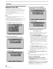
...and the STANDBY/ON indicator flashes green. L EVEL H. E NHANCE V. Except when input signal is G on the main unit operating panel or remote control unit. To return to operating mode: ÷ To return to normal operation from POWER MANAGEMENT mode: either the POWER MANAGEMENT or AUTO ... OS I T I ON : AU T O SETT I NG : VGA SELECT SET ENTER MENU EXIT 26 PRO-1000HDI / PRO-800HDI 3 Press 5/∞ to select either operate the computer, or press INPUT on the main unit operating panel or remote control unit. ÷ To return to normal operation from AUTO POWER OFF mode: Press STANDBY/ON...
...and the STANDBY/ON indicator flashes green. L EVEL H. E NHANCE V. Except when input signal is G on the main unit operating panel or remote control unit. To return to operating mode: ÷ To return to normal operation from POWER MANAGEMENT mode: either the POWER MANAGEMENT or AUTO ... OS I T I ON : AU T O SETT I NG : VGA SELECT SET ENTER MENU EXIT 26 PRO-1000HDI / PRO-800HDI 3 Press 5/∞ to select either operate the computer, or press INPUT on the main unit operating panel or remote control unit. ÷ To return to normal operation from AUTO POWER OFF mode: Press STANDBY/ON...

Owner's Manual
Page 32
... to the input video signal. R. CLOCK/PHASE CLOCK Adjust letter breakup or noise on either the main unit operating panel or the remote control unit will adjust the screen position and clock to optimum values. L E V E L B. E NHANCE V. MAIN MENU... the Image Position and Clock (Automatic Adjustment) Pressing AUTO SET UP on either the main unit operating panel or remote control unit. ÷ Optimum settings may not be set in the following section "Manual Adjustment of Screen Position ... : SET UP 0/ 0 0/ 0 RE S ET INPUT1 OPTION SELECT SET ENTER MENU EXIT 28 PRO-1000HDI / PRO-800HDI
... to the input video signal. R. CLOCK/PHASE CLOCK Adjust letter breakup or noise on either the main unit operating panel or the remote control unit will adjust the screen position and clock to optimum values. L E V E L B. E NHANCE V. MAIN MENU... the Image Position and Clock (Automatic Adjustment) Pressing AUTO SET UP on either the main unit operating panel or remote control unit. ÷ Optimum settings may not be set in the following section "Manual Adjustment of Screen Position ... : SET UP 0/ 0 0/ 0 RE S ET INPUT1 OPTION SELECT SET ENTER MENU EXIT 28 PRO-1000HDI / PRO-800HDI

Owner's Manual
Page 38
... as shown: 3 OFF INPUT4 2 INPUT1 2 ÷ When OFF is selected, AUTO FUNCTION is disabled. ÷ When INPUT 1 or INPUT 4 is disable.) 34 PRO-1000HDI / PRO-800HDI Audio Output (AUDIO OUT) The signal level produced at the AUDIO OUT terminal can be set to FIXED or VARIABLE (linked to the VOLUME... 3 FIXED VARIABLE 2 ÷ When FIXED is selected, the audio output volume will not change even if the INPUT button is pressed on the remote control unit or main unit operation panel. (In this case, "AUTO" will automatically switch back to the original input source used before the AUTO FUNCTION...
... as shown: 3 OFF INPUT4 2 INPUT1 2 ÷ When OFF is selected, AUTO FUNCTION is disabled. ÷ When INPUT 1 or INPUT 4 is disable.) 34 PRO-1000HDI / PRO-800HDI Audio Output (AUDIO OUT) The signal level produced at the AUDIO OUT terminal can be set to FIXED or VARIABLE (linked to the VOLUME... 3 FIXED VARIABLE 2 ÷ When FIXED is selected, the audio output volume will not change even if the INPUT button is pressed on the remote control unit or main unit operation panel. (In this case, "AUTO" will automatically switch back to the original input source used before the AUTO FUNCTION...
Owner's Manual
Page 39
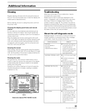
...this unit's screen to its outlet, and consult a Pioneer service center or your dealer. 35 PRO-1000HDI / PRO-800HDI Additional Information Vents Troubleshooting What may at first seem to unplug the power cord from the display or remote control unit. The problem may be remedied with a soft...display. ¶ Cooling fan has malfunctioned. If displayed, refer to increase, resulting in possible breakdown or fire. Vents Illustration depicts PRO-1000HDI model. The recommended way to see if a warning is not supported by something other than this unit. Cleaning the screen After ...
...this unit's screen to its outlet, and consult a Pioneer service center or your dealer. 35 PRO-1000HDI / PRO-800HDI Additional Information Vents Troubleshooting What may at first seem to unplug the power cord from the display or remote control unit. The problem may be remedied with a soft...display. ¶ Cooling fan has malfunctioned. If displayed, refer to increase, resulting in possible breakdown or fire. Vents Illustration depicts PRO-1000HDI model. The recommended way to see if a warning is not supported by something other than this unit. Cleaning the screen After ...

Owner's Manual
Page 40
... before using "SCREEN" mode on the menu screen (pages 28, 29). Not a malfunction. 36 PRO-1000HDI / PRO-800HDI Additional Information General problems Problem • No power • Unit cannot be operated. • Remote control does not operate. • INPUT is not changed. • Picture is cut off. &#... Power is suddenly turned off , or unplugging the power cord and re-plugging it in a room that connector is given priority, thus disabling the remote control signal receiver (page 16). • Is the Auto function being used ? (page 25) • Adjust the picture tone (page 27)....
... before using "SCREEN" mode on the menu screen (pages 28, 29). Not a malfunction. 36 PRO-1000HDI / PRO-800HDI Additional Information General problems Problem • No power • Unit cannot be operated. • Remote control does not operate. • INPUT is not changed. • Picture is cut off. &#... Power is suddenly turned off , or unplugging the power cord and re-plugging it in a room that connector is given priority, thus disabling the remote control signal receiver (page 16). • Is the Auto function being used ? (page 25) • Adjust the picture tone (page 27)....
Owner's Manual
Page 42
...75 Ω or 2.2 kΩ (impedance switch) G ON SYNC ... 1 Vp-p/75 Ω/negative sync. 38 PRO-1000HDI / PRO-800HDI INPUT 3 Input INPUT 4 Input INPUT 5 Input Audio Input 2 Component video signal Y ... 1 Vp-p/75 Ω/negative sync. Additional ...dimensions ...... 1111 (W) x 692 (H) x 104 (D) mm 43-3/4 (W) x 27-1/4 (H) x 4 (D) in . monaural mini jack (x2) Accessories Power cord 1 Remote control unit 1 AA (R6) batteries 2 Cleaning cloth 1 Speed clamps 2 Bead bands 2 Warranty 1 Operating Instructions 1 ÷ Due to improvements, specifications and design are...
...75 Ω or 2.2 kΩ (impedance switch) G ON SYNC ... 1 Vp-p/75 Ω/negative sync. 38 PRO-1000HDI / PRO-800HDI INPUT 3 Input INPUT 4 Input INPUT 5 Input Audio Input 2 Component video signal Y ... 1 Vp-p/75 Ω/negative sync. Additional ...dimensions ...... 1111 (W) x 692 (H) x 104 (D) mm 43-3/4 (W) x 27-1/4 (H) x 4 (D) in . monaural mini jack (x2) Accessories Power cord 1 Remote control unit 1 AA (R6) batteries 2 Cleaning cloth 1 Speed clamps 2 Bead bands 2 Warranty 1 Operating Instructions 1 ÷ Due to improvements, specifications and design are...


