Owner's Manual
Page 3
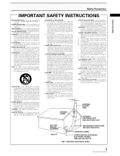
... an antenna discharge unit, size of grounding conductors, location of antenna-discharge unit, connection to lightning and power-line surges. Adjust only those controls that the product is grounded so as recommended by the manufacturer. HEAT - The appliance should be installed in a wet basement; This is a safety feature. Refer all servicing to replace your obsolete outlet. this product on the product. RETAIN INSTRUCTIONS...
... an antenna discharge unit, size of grounding conductors, location of antenna-discharge unit, connection to lightning and power-line surges. Adjust only those controls that the product is grounded so as recommended by the manufacturer. HEAT - The appliance should be installed in a wet basement; This is a safety feature. Refer all servicing to replace your obsolete outlet. this product on the product. RETAIN INSTRUCTIONS...
Owner's Manual
Page 5
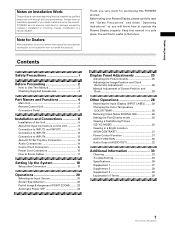
... Automatic Power OFF 24 Display Panel Adjustments 25 Adjusting the Picture Quality 25 Adjusting the Image Position and Clock (Automatic Adjustment 26 Manual Adjustment of Screen Position and Clock 26 Other Operations 28 Rewriting the Input Display (INPUT LABEL) ........ 28 Changing the Color Temperature (COLOR TEMP 29 Reducing Video Noise (DIGITAL NR 29 Setting the PureCinema mode 30 Viewing a Fast Moving Picture (3D Y/C MODE 30 Viewing in a Bright Location (HIGH CONTRAST 31 Power Control Function 31 AUTO FUNCTION 32 Audio Output (AUDIO OUT...
... Automatic Power OFF 24 Display Panel Adjustments 25 Adjusting the Picture Quality 25 Adjusting the Image Position and Clock (Automatic Adjustment 26 Manual Adjustment of Screen Position and Clock 26 Other Operations 28 Rewriting the Input Display (INPUT LABEL) ........ 28 Changing the Color Temperature (COLOR TEMP 29 Reducing Video Noise (DIGITAL NR 29 Setting the PureCinema mode 30 Viewing a Fast Moving Picture (3D Y/C MODE 30 Viewing in a Bright Location (HIGH CONTRAST 31 Power Control Function 31 AUTO FUNCTION 32 Audio Output (AUDIO OUT...
Owner's Manual
Page 6
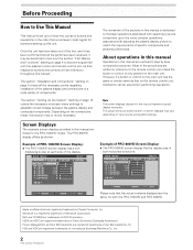
... with adjusting the plasma display picture to match the requirements of Microsoft Corporation. MAIN MENU PICTURE SCREEN CONT RAST BR I GHT . E NHANCE V. Microsoft is a registered trademark of specific components and personal preferences. Depending on the connections made, this manual is dedicated to the basic operations associated with selecting a source component up to the more complex operations associated with the plasma monitor and remote control unit...
... with adjusting the plasma display picture to match the requirements of Microsoft Corporation. MAIN MENU PICTURE SCREEN CONT RAST BR I GHT . E NHANCE V. Microsoft is a registered trademark of specific components and personal preferences. Depending on the connections made, this manual is dedicated to the basic operations associated with selecting a source component up to the more complex operations associated with the plasma monitor and remote control unit...
Owner's Manual
Page 9
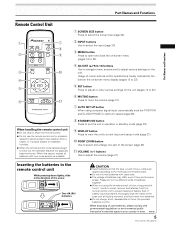
.... 1 SCREEN SIZE button Press to select the screen size (page 22). 2 INPUT buttons Use to select the input (page 20). 3 MENU button Press to open and close the on-screen menu (pages 18 to 32). 4 ADJUST (5/∞/3/2) buttons Use to navigate menu screens and to adjust various settings on the unit (pages 18 to 32). 6 MUTING button Press to mute the volume (page 21). 7 AUTO SET UP button When using the remote control unit for a long period of time (1 month...
.... 1 SCREEN SIZE button Press to select the screen size (page 22). 2 INPUT buttons Use to select the input (page 20). 3 MENU button Press to open and close the on-screen menu (pages 18 to 32). 4 ADJUST (5/∞/3/2) buttons Use to navigate menu screens and to adjust various settings on the unit (pages 18 to 32). 6 MUTING button Press to mute the volume (page 21). 7 AUTO SET UP button When using the remote control unit for a long period of time (1 month...
Owner's Manual
Page 10
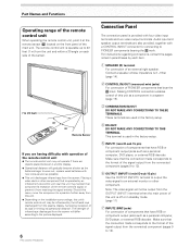
...) 30˚ S-VIDEO VIDEO 30˚ Remote Sensor If you are having difficulty with four video input terminals and two video output terminals. The strength of infrared rays discharged from the screen will differ according to the picture displayed. 6 PRO-1000HD / PRO-800HD Connection Panel The connection panel is operable up to 23 feet (7 m) from receiving the signal entirely. Making CONTROL connection enables control of this unit as a component in standby mode. (page 11...
...) 30˚ S-VIDEO VIDEO 30˚ Remote Sensor If you are having difficulty with four video input terminals and two video output terminals. The strength of infrared rays discharged from the screen will differ according to the picture displayed. 6 PRO-1000HD / PRO-800HD Connection Panel The connection panel is operable up to 23 feet (7 m) from receiving the signal entirely. Making CONTROL connection enables control of this unit as a component in standby mode. (page 11...
Owner's Manual
Page 11
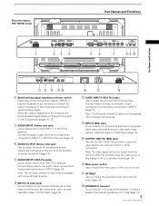
...). Connect a speaker that have an S-video output terminal such as a video deck, video camera, LaserDisc player, or DVD player (page 13). @ OUTPUT (INPUT4) (BNC jack) Use the OUTPUT (INPUT4) terminal to output the video signal to obtain sound when INPUT1 or INPUT2 is off . $ AC INLET Use to connect the supplied power cord to match the output impedance of 8 -16 Ω (page 14). 7 PRO-1000HD / PRO-800HD Connect these terminals to the audio output connectors of components connected to...
...). Connect a speaker that have an S-video output terminal such as a video deck, video camera, LaserDisc player, or DVD player (page 13). @ OUTPUT (INPUT4) (BNC jack) Use the OUTPUT (INPUT4) terminal to output the video signal to obtain sound when INPUT1 or INPUT2 is off . $ AC INLET Use to connect the supplied power cord to match the output impedance of 8 -16 Ω (page 14). 7 PRO-1000HD / PRO-800HD Connect these terminals to the audio output connectors of components connected to...
Owner's Manual
Page 15
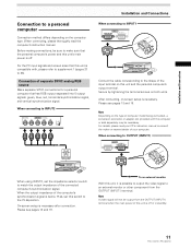
....Ω2 Installation and Connections When connecting to INPUT1 INPUT1 OUTPUT ANALOG RGB (ANALOG RGB) Connect the cable corresponding to the shape of the input terminal on this switch to make sure that has RGB output separated into 5 output signals: green, blue, red, horizontal synchronization signal, and vertical synchronization signal. When the output impedance of the computer's synchronization signal is possible to output the video signal to 38). On-screen setup is off . When connecting, please...
....Ω2 Installation and Connections When connecting to INPUT1 INPUT1 OUTPUT ANALOG RGB (ANALOG RGB) Connect the cable corresponding to the shape of the input terminal on this switch to make sure that has RGB output separated into 5 output signals: green, blue, red, horizontal synchronization signal, and vertical synchronization signal. When the output impedance of the computer's synchronization signal is possible to output the video signal to 38). On-screen setup is off . When connecting, please...

Owner's Manual
Page 22
... is necessary. Setting Up the System Setup after Connection After components have been connected to INPUT1 or INPUT2, on the unit's main power. It is not supported when inputting a computer signal, or when the Screen Mode setting has been used to select a mode other than VIDEO. 1 Switch the main power switch on the connection panel to the on position to turn on -screen setup is connected, set to select the display mode. MAIN MENU INPUT1 PICTURE SET UP OPTION...
... is necessary. Setting Up the System Setup after Connection After components have been connected to INPUT1 or INPUT2, on the unit's main power. It is not supported when inputting a computer signal, or when the Screen Mode setting has been used to select a mode other than VIDEO. 1 Switch the main power switch on the connection panel to the on position to turn on -screen setup is connected, set to select the display mode. MAIN MENU INPUT1 PICTURE SET UP OPTION...
Owner's Manual
Page 23
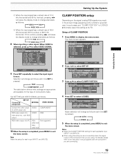
... VIDEO SIGNAL as follows each time SET is selected), press 5/∞ to select VIDEO SIGNAL. Setting Up the System CLAMP POSITION setup Depending on the signal, analog RGB signals may result in the screen image appearing with the component you are using this setting at AUTO. MAIN MENU PICTURE SCREEN CONT RAST BR I GNA L : RGB SELECT SET CHANGE MENU EXIT 9 Press SET repeatedly to select the input signal format. In such cases, set "CLAMP POSITION" to LOCKED...
... VIDEO SIGNAL as follows each time SET is selected), press 5/∞ to select VIDEO SIGNAL. Setting Up the System CLAMP POSITION setup Depending on the signal, analog RGB signals may result in the screen image appearing with the component you are using this setting at AUTO. MAIN MENU PICTURE SCREEN CONT RAST BR I GNA L : RGB SELECT SET CHANGE MENU EXIT 9 Press SET repeatedly to select the input signal format. In such cases, set "CLAMP POSITION" to LOCKED...

Owner's Manual
Page 24
... 2,5 3 S-VIDEO VIDEO 2,5 3 FULL I NPUT1 CAUT I O N OUT OF R ANG E f H : 75. 7 kH z f V :120. 0 Hz ---- 4 Main Unit Operating Panel Remote Control Unit 1 Switch the main power switch on the main unit to the on . on the screen. The STANDBY/ON indicator lights red. 2 Press STANDBY/ON to adjust the volume. The STANDBY/ON indicator may cause a phenomenon known as "screen burn" which leaves a ghost, or residual, image of the picture on the remote control unit...
... 2,5 3 S-VIDEO VIDEO 2,5 3 FULL I NPUT1 CAUT I O N OUT OF R ANG E f H : 75. 7 kH z f V :120. 0 Hz ---- 4 Main Unit Operating Panel Remote Control Unit 1 Switch the main power switch on the main unit to the on . on the screen. The STANDBY/ON indicator lights red. 2 Press STANDBY/ON to adjust the volume. The STANDBY/ON indicator may cause a phenomenon known as "screen burn" which leaves a ghost, or residual, image of the picture on the remote control unit...

Owner's Manual
Page 26
... the source. [PRO-1000HD] A 480 lines 768 lines 640 dots 1280 dots (Illustration shows 640 x 480 input.) [PRO-800HD] * The PRO-800HD is presented with an expansive powerful image. 4:3 FULL Suitable for wide screen images (squeeze). ZOOM Mainly suitable for information regarding screen sizes supported by each time the power is used to display a non-wide screen 4:3 picture fully on a wide screen, a portion of the picture may be changed to FULL. 22 PRO-1000HD / PRO-800HD During video signal input...
... the source. [PRO-1000HD] A 480 lines 768 lines 640 dots 1280 dots (Illustration shows 640 x 480 input.) [PRO-800HD] * The PRO-800HD is presented with an expansive powerful image. 4:3 FULL Suitable for wide screen images (squeeze). ZOOM Mainly suitable for information regarding screen sizes supported by each time the power is used to display a non-wide screen 4:3 picture fully on a wide screen, a portion of the picture may be changed to FULL. 22 PRO-1000HD / PRO-800HD During video signal input...

Owner's Manual
Page 28
... preceding item. ÷ Always turn off the plasma display's main power switch when not using the display for extended periods of time. 1 Press MENU to exit the menu screen. L EVEL G. MAIN MENU PICTURE SCREEN CONT RAST BR I NG : VGA 4 Press SET to INPUT 1. ÷ The auto-power-off function can be set individually for 8 seconds, after which the display automatically enters the power-saving mode (*1) and the STANDBY/ON indicator flashes green. ENHANCE :0 :0 : +60 : +60...
... preceding item. ÷ Always turn off the plasma display's main power switch when not using the display for extended periods of time. 1 Press MENU to exit the menu screen. L EVEL G. MAIN MENU PICTURE SCREEN CONT RAST BR I NG : VGA 4 Press SET to INPUT 1. ÷ The auto-power-off function can be set individually for 8 seconds, after which the display automatically enters the power-saving mode (*1) and the STANDBY/ON indicator flashes green. ENHANCE :0 :0 : +60 : +60...
Owner's Manual
Page 30
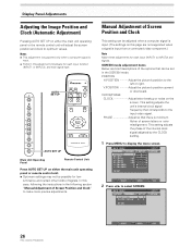
... the instructions in the SCREEN mode. Display Panel Adjustments Adjusting the Image Position and Clock (Automatic Adjustment) Pressing AUTO SET UP on the screen. AUTO SET UP S-VIDEO VIDEO AUTO SET UP Main Unit Operating Panel Remote Control Unit Press AUTO SET UP on this page are brief descriptions of Screen Position and Clock" to INPUT2) and signals. L EVEL G. L E V E L B. POSITION H.POSITION Adjust the picture's position to the input video signal. SCREEN mode adjustment items Below are not supported when a signal is minimum flicker of signals. PHASE Adjust...
... the instructions in the SCREEN mode. Display Panel Adjustments Adjusting the Image Position and Clock (Automatic Adjustment) Pressing AUTO SET UP on the screen. AUTO SET UP S-VIDEO VIDEO AUTO SET UP Main Unit Operating Panel Remote Control Unit Press AUTO SET UP on this page are brief descriptions of Screen Position and Clock" to INPUT2) and signals. L EVEL G. L E V E L B. POSITION H.POSITION Adjust the picture's position to the input video signal. SCREEN mode adjustment items Below are not supported when a signal is minimum flicker of signals. PHASE Adjust...
Owner's Manual
Page 33
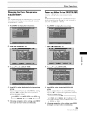
Other Operations Changing the Color Temperature (COLOR TEMP) Note Color temperature settings are supported only with input signals from a video device. MAIN MENU PICTURE CONT RAST BR I GNAL : RGB SELECT SET CHANGE MENU EXIT 4 Press SET to select the desired DIGITAL NR setting. INPUT4). 1 Press MENU to display the menu screen. MAIN MENU INPUT1 PICTURE SET UP OPTION I NPUT L ABEL : I NPUT 1 AUT O P OWER OF F : OF F COL OR T EMP : M I DDL E D I G I T A L NR : L OW H I GH CON TRAS T : OF...
Other Operations Changing the Color Temperature (COLOR TEMP) Note Color temperature settings are supported only with input signals from a video device. MAIN MENU PICTURE CONT RAST BR I GNAL : RGB SELECT SET CHANGE MENU EXIT 4 Press SET to select the desired DIGITAL NR setting. INPUT4). 1 Press MENU to display the menu screen. MAIN MENU INPUT1 PICTURE SET UP OPTION I NPUT L ABEL : I NPUT 1 AUT O P OWER OF F : OF F COL OR T EMP : M I DDL E D I G I T A L NR : L OW H I GH CON TRAS T : OF...
Owner's Manual
Page 35
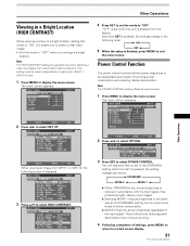
... menu screen. L E V E L B. Each time SET is pressed, the setting changes as follows: 3 STANDARD MODE 2 2 MODE 1 2 ÷ When STANDARD is set to select POWER CONTROL. INPUT 4) used. 1 Press MENU to select SET UP. "OFF" is displayed. MAIN MENU INPUT1 PICTURE SCREEN CONT RAST BR I GHT . ENHANCE :0 :0 : +60 : +60 : +60 :0 :0 SET UP OPTION RE S ET SELECT SET ENTER MENU EXIT 2 Press 2/3 to display the menu screen. This is supported only when selecting a video input signal from the factory. The menu screen appears. Note The POWER CONTROL setting...
... menu screen. L E V E L B. Each time SET is pressed, the setting changes as follows: 3 STANDARD MODE 2 2 MODE 1 2 ÷ When STANDARD is set to select POWER CONTROL. INPUT 4) used. 1 Press MENU to select SET UP. "OFF" is displayed. MAIN MENU INPUT1 PICTURE SCREEN CONT RAST BR I GHT . ENHANCE :0 :0 : +60 : +60 : +60 :0 :0 SET UP OPTION RE S ET SELECT SET ENTER MENU EXIT 2 Press 2/3 to display the menu screen. This is supported only when selecting a video input signal from the factory. The menu screen appears. Note The POWER CONTROL setting...
Owner's Manual
Page 36
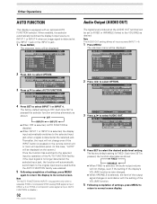
... display to normal screen display. L EVEL G. L EVEL H. MAIN MENU INPUT1 PICTURE SCREEN SET UP OPTION POWER CONT R OL : S T A NDA RD AUT O F U NCT I ON : OF F AUD I O OUT :F I XED 3 Press 5/∞ to INPUT 1 or INPUT 4 when an image signal is pressed on the remote control unit or main unit operation panel. (In this case, "AUTO" will be displayed on SYNC or component video signal is input, AUTO FUNCTION is disable.) 32 PRO-1000HD / PRO-800HD Audio Output (AUDIO OUT) The signal...
... display to normal screen display. L EVEL G. L EVEL H. MAIN MENU INPUT1 PICTURE SCREEN SET UP OPTION POWER CONT R OL : S T A NDA RD AUT O F U NCT I ON : OF F AUD I O OUT :F I XED 3 Press 5/∞ to INPUT 1 or INPUT 4 when an image signal is pressed on the remote control unit or main unit operation panel. (In this case, "AUTO" will be displayed on SYNC or component video signal is input, AUTO FUNCTION is disable.) 32 PRO-1000HD / PRO-800HD Audio Output (AUDIO OUT) The signal...
Owner's Manual
Page 37
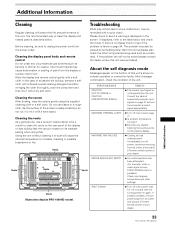
... a Pioneer service center or your dealer. 33 PRO-1000HD / PRO-800HD Additional Information Vents Vents Vents ERROR INVALID KEY ENTRY ¶ An invalid operation has been attempted. (For example, when a video signal is input, POINT ZOOM button is listed on again. If problem persists, remove power plug from the display or remote control unit. Please check to see if the problem is pressed.) Check input signals, connections and other components being used such...
... a Pioneer service center or your dealer. 33 PRO-1000HD / PRO-800HD Additional Information Vents Vents Vents ERROR INVALID KEY ENTRY ¶ An invalid operation has been attempted. (For example, when a video signal is input, POINT ZOOM button is listed on again. If problem persists, remove power plug from the display or remote control unit. Please check to see if the problem is pressed.) Check input signals, connections and other components being used such...

Owner's Manual
Page 38
Additional Information General problems Problem • No power • Unit cannot be operated. • Remote control does not operate. • INPUT is not changed. • Picture is cut off. • Strange color, light color, or dark, or color misalignment • Power is set to ON? (page 24). • Condensation has formed on internal parts due to another screen size (page 22). • Are SCREEN mode adjustments such as lightning, static electricity...
Additional Information General problems Problem • No power • Unit cannot be operated. • Remote control does not operate. • INPUT is not changed. • Picture is cut off. • Strange color, light color, or dark, or color misalignment • Power is set to ON? (page 24). • Condensation has formed on internal parts due to another screen size (page 22). • Are SCREEN mode adjustments such as lightning, static electricity...
Owner's Manual
Page 39
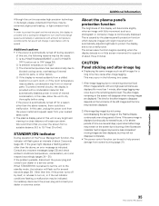
... plasma panel's protection function The brightness of this unit is moved suddenly from a suitable distance (9.8 to 19.7 feet (3 to the standby mode, the indicator will flash red for more than this, if the power turns off during operation of this display will deteriorate slightly when an image with very high peak luminance are later displayed, but they had been displayed. 2. If the green light displays a flashing pattern...
... plasma panel's protection function The brightness of this unit is moved suddenly from a suitable distance (9.8 to 19.7 feet (3 to the standby mode, the indicator will flash red for more than this, if the power turns off during operation of this display will deteriorate slightly when an image with very high peak luminance are later displayed, but they had been displayed. 2. If the green light displays a flashing pattern...
Owner's Manual
Page 40
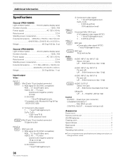
... mini jack (x2) Accessories Power cord 1 Remote control unit 1 AA (R6) batteries 2 Cleaning cloth 1 Speed clamps 2 Bead bands 2 Warranty 1 Operating Instructions 1 ÷ Due to improvements, specifications and design are subject to change without notice. Weight 46.5 kg (102 lbs. 8 oz) General (PRO-800HD) Light emission panel 43 inch plasma display panel Number of pixels 1280 x 768 Power supply AC 120 V, 60 Hz Rated current 3.2 A Standby power consumption 1 W External dimensions ... 1259 (W) x 776 (H) x 104.7 (D) mm...
... mini jack (x2) Accessories Power cord 1 Remote control unit 1 AA (R6) batteries 2 Cleaning cloth 1 Speed clamps 2 Bead bands 2 Warranty 1 Operating Instructions 1 ÷ Due to improvements, specifications and design are subject to change without notice. Weight 46.5 kg (102 lbs. 8 oz) General (PRO-800HD) Light emission panel 43 inch plasma display panel Number of pixels 1280 x 768 Power supply AC 120 V, 60 Hz Rated current 3.2 A Standby power consumption 1 W External dimensions ... 1259 (W) x 776 (H) x 104.7 (D) mm...


