Owner's Manual
Page 2
... the FCC Rules. If this manual. CUSTOMER SUPPORT DIVISION P.O. Connect the equipment into an outlet on , the user is encouraged to try to which can radiate radio frequency energy and, if not installed and used in this equipment does cause harmful interference to provide reasonable protection against harmful interference in a particular installation. After-sales service for Pioneer products Please contact the dealer or...
... the FCC Rules. If this manual. CUSTOMER SUPPORT DIVISION P.O. Connect the equipment into an outlet on , the user is encouraged to try to which can radiate radio frequency energy and, if not installed and used in this equipment does cause harmful interference to provide reasonable protection against harmful interference in a particular installation. After-sales service for Pioneer products Please contact the dealer or...
Owner's Manual
Page 3
.... ! Ensure that you have established a comfortable sound level, set the dial and leave it comfortably and clearly, without affecting your hearing. If the screw for your dealer or nearest authorized Pioneer Service Station. ware updates) for the ground wire loosens or falls out, it at a low setting. ! Connect the battery wire directly to the car battery positive terminal + and the ground wire to your sensitive hearing. Learn about product...
.... ! Ensure that you have established a comfortable sound level, set the dial and leave it comfortably and clearly, without affecting your hearing. If the screw for your dealer or nearest authorized Pioneer Service Station. ware updates) for the ground wire loosens or falls out, it at a low setting. ! Connect the battery wire directly to the car battery positive terminal + and the ground wire to your sensitive hearing. Learn about product...
Owner's Manual
Page 4
Do not allow parts such as extra screws to prevent equipment malfunction. In the event of the separately sold battery wire or the amplifier fuse blows. If you are short-circuited. - If the temperature gets too high, the power indicator will turn off and check the power supply and speaker connections. Always keep the volume low enough to record this occurs, switch the system power off and the am- gine...
Do not allow parts such as extra screws to prevent equipment malfunction. In the event of the separately sold battery wire or the amplifier fuse blows. If you are short-circuited. - If the temperature gets too high, the power indicator will turn off and check the power supply and speaker connections. Always keep the volume low enough to record this occurs, switch the system power off and the am- gine...
Owner's Manual
Page 5
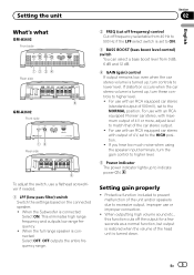
... when using the speaker input terminals, turn the gain control to higher level. 5 Power indicator The power indicator lights up to lower level. OFF outputs the entire frequency range. For use with an RCA equipped car stereo (standard output of the head unit is connected: Select OFF. To adjust the switch, use or improper connection. ! When the Subwoofer is turned up, turn these controls to match that of 4 V or more, adjust level to higher level. ! For use with an RCA equipped Pioneer car stereo, with output of the unit and/or speakers due...
... when using the speaker input terminals, turn the gain control to higher level. 5 Power indicator The power indicator lights up to lower level. OFF outputs the entire frequency range. For use with an RCA equipped car stereo (standard output of the head unit is connected: Select OFF. To adjust the switch, use or improper connection. ! When the Subwoofer is turned up, turn these controls to match that of 4 V or more, adjust level to higher level. ! For use with an RCA equipped Pioneer car stereo, with output of the unit and/or speakers due...
Owner's Manual
Page 6
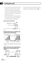
... head unit at high volume using amplifier gain control 6 En Section 02 Setting the unit ! To ensure continuous sound output with little increase in sound output may indicate improper setting of this unit Preout level: 2 V (Standard: 500 mV) Preout level: 4 V If the signal waveform is distorted due to control excess output. ! Above illustration shows NORMAL gain setting. Gain control of the gain control. In such cases, please contact the nearest authorized Pioneer Service Station. Despite correct volume and gain settings, the unit sound still cuts...
... head unit at high volume using amplifier gain control 6 En Section 02 Setting the unit ! To ensure continuous sound output with little increase in sound output may indicate improper setting of this unit Preout level: 2 V (Standard: 500 mV) Preout level: 4 V If the signal waveform is distorted due to control excess output. ! Above illustration shows NORMAL gain setting. Gain control of the gain control. In such cases, please contact the nearest authorized Pioneer Service Station. Despite correct volume and gain settings, the unit sound still cuts...
Owner's Manual
Page 7
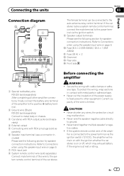
... following section for speaker connection instructions. If the system remote control wire of the ampli- fier is connected to Connections when using the speaker input wire on page 9. a Fuse 30 A × 2 (GM-A5602) / 25 A × 1 (GMA3602) b Fuse (30 A) × 2 c Grommet d Rear side e Front side 1 Special red battery wire RD-223 (sold separately) After completing all other equipment. Connecting the units Section 03 English Connection diagram The female terminal can be connected to the system remote control terminal of the car stereo.
... following section for speaker connection instructions. If the system remote control wire of the ampli- fier is connected to Connections when using the speaker input wire on page 9. a Fuse 30 A × 2 (GM-A5602) / 25 A × 1 (GMA3602) b Fuse (30 A) × 2 c Grommet d Rear side e Front side 1 Special red battery wire RD-223 (sold separately) After completing all other equipment. Connecting the units Section 03 English Connection diagram The female terminal can be connected to the system remote control terminal of the car stereo.
Owner's Manual
Page 8
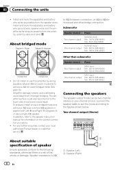
... amplifier surface could also become hot to achieve a 2 W (or lower) bridged mode (Diagram B). For any further enquiries, contact your local authorized Pioneer dealer or customer service. Speaker impedance is a risk of speaker 2 Ensure speakers conform to the speaker instruction manual for information on the correct connection procedure. ! Other than subwoofer Speaker channel Two-channel output One-channel output Power MAX input: Min. 300 W (GM-A5602) Min. 120 W (GM-A3602) MAX input: Min. 900 W (GM-A5602) Min. 400 W (GM-A3602) Connecting the speakers The speaker output mode...
... amplifier surface could also become hot to achieve a 2 W (or lower) bridged mode (Diagram B). For any further enquiries, contact your local authorized Pioneer dealer or customer service. Speaker impedance is a risk of speaker 2 Ensure speakers conform to the speaker instruction manual for information on the correct connection procedure. ! Other than subwoofer Speaker channel Two-channel output One-channel output Power MAX input: Min. 300 W (GM-A5602) Min. 120 W (GM-A3602) MAX input: Min. 900 W (GM-A5602) Min. 400 W (GM-A3602) Connecting the speakers The speaker output mode...
Owner's Manual
Page 9
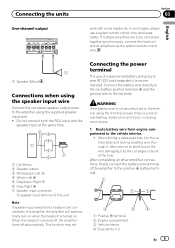
... securely fixed to the terminal using the supplied speaker input wire. ! Connect the battery wire directly to the car battery positive terminal + and the ground wire to short-circuit the wire damaging it , take care not to the car body. Note If speaker input wires from a headunit are to be connected together synchronously, connect the head unit and all other amplifier connections, finally connect the battery wire terminal of a special red battery and ground wire RD-223 (sold separately). This function may not Connecting the power terminal The use a system remote control wire...
... securely fixed to the terminal using the supplied speaker input wire. ! Connect the battery wire directly to the car battery positive terminal + and the ground wire to short-circuit the wire damaging it , take care not to the car body. Note If speaker input wires from a headunit are to be connected together synchronously, connect the head unit and all other amplifier connections, finally connect the battery wire terminal of a special red battery and ground wire RD-223 (sold separately). This function may not Connecting the power terminal The use a system remote control wire...
Owner's Manual
Page 10
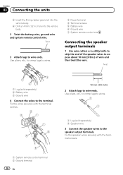
...) 2 Speaker wire 3 Connect the speaker wires to the speaker output terminals. Twist 3 Attach lugs to wire ends. Fix the speaker wires securely with the terminal screws. 2 Attach lugs to wire ends. Fix the wires securely with the terminal screws. 1 System remote control terminal 2 Ground terminal 10 En Use pliers, etc., to crimp lugs to wires. 3 Power terminal 4 Terminal screws 5 Battery wire 6 Ground wire 7 System remote control wire Connecting the speaker output terminals 1 Use wire cutters or a utility knife to strip the end of the speaker wires to the terminal. Use pliers...
...) 2 Speaker wire 3 Connect the speaker wires to the speaker output terminals. Twist 3 Attach lugs to wire ends. Fix the speaker wires securely with the terminal screws. 2 Attach lugs to wire ends. Fix the wires securely with the terminal screws. 1 System remote control terminal 2 Ground terminal 10 En Use pliers, etc., to crimp lugs to wires. 3 Power terminal 4 Terminal screws 5 Battery wire 6 Ground wire 7 System remote control wire Connecting the speaker output terminals 1 Use wire cutters or a utility knife to strip the end of the speaker wires to the terminal. Use pliers...
Owner's Manual
Page 11
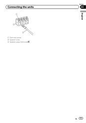
Connecting the units 1 Terminal screws 2 Speaker wires 3 Speaker output terminals English Section 03 En 11
Connecting the units 1 Terminal screws 2 Speaker wires 3 Speaker output terminals English Section 03 En 11
Owner's Manual
Page 12
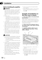
... short-circuit may damage internal parts of installation on the car model. Place all cables away from damage. Example of the amplifier, or become loose causing the amplifier to install the amplifier, always confirm no parts are to installation in front of the driver's seat. ! If any wire. fuel/brake lines, wiring) from hot places, such as near the heater outlet. ! Protection function may activate to protect the amplifier against...
... short-circuit may damage internal parts of installation on the car model. Place all cables away from damage. Example of the amplifier, or become loose causing the amplifier to install the amplifier, always confirm no parts are to installation in front of the driver's seat. ! If any wire. fuel/brake lines, wiring) from hot places, such as near the heater outlet. ! Protection function may activate to protect the amplifier against...
Owner's Manual
Page 13
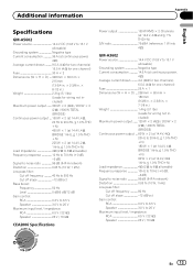
... pass filter: Cut off frequency 40 Hz to 500 Hz Cut off slope 12 dB/oct Bass boost: Frequency 50 Hz Level 0 dB/6 dB/12 dB Gain control: RCA 0.3 V to 6.5 V Speaker 3.0 V to 26 V Maximum input level / impedance: RCA 6.5 V / 22 kW Speaker 26 V / 16 kW CEA2006 Specifications Power output 150 W RMS × 2 Channels (at 14.4 V, 4 W and ≦ 1 % THD+N) S/N ratio 75 dBA (reference: 1 W into 4 W) GM-A3602 Power source 14.4 V DC (10.8 V to 15.1 V allowable) Grounding...
... pass filter: Cut off frequency 40 Hz to 500 Hz Cut off slope 12 dB/oct Bass boost: Frequency 50 Hz Level 0 dB/6 dB/12 dB Gain control: RCA 0.3 V to 6.5 V Speaker 3.0 V to 26 V Maximum input level / impedance: RCA 6.5 V / 22 kW Speaker 26 V / 16 kW CEA2006 Specifications Power output 150 W RMS × 2 Channels (at 14.4 V, 4 W and ≦ 1 % THD+N) S/N ratio 75 dBA (reference: 1 W into 4 W) GM-A3602 Power source 14.4 V DC (10.8 V to 15.1 V allowable) Grounding...
Owner's Manual
Page 14
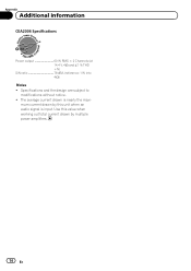
mum current drawn by multiple power amplifiers. 14 En Use this value when working out total current drawn by this unit when an audio signal is nearly the maxi- Appendix Additional information CEA2006 Specifications Power output 60 W RMS × 2 Channels (at 14.4 V, 4 W and ≦ 1 % THD +N) S/N ratio 78 dBA (reference: 1 W into 4 W) Notes ! Specifications and the design are subject to modifications without notice. ! The average current drawn is input.
mum current drawn by multiple power amplifiers. 14 En Use this value when working out total current drawn by this unit when an audio signal is nearly the maxi- Appendix Additional information CEA2006 Specifications Power output 60 W RMS × 2 Channels (at 14.4 V, 4 W and ≦ 1 % THD +N) S/N ratio 78 dBA (reference: 1 W into 4 W) Notes ! Specifications and the design are subject to modifications without notice. ! The average current drawn is input.
Owner's Manual
Page 44
...-01, Singapore 159936 TEL: 65-6472-7555 PIONEER ELECTRONICS AUSTRALIA PTY. All rights reserved. ã 2013 PIONEER CORPORATION. Tous droits de reproduction et de traduction réservés. P.O. LTD. 5 Arco Lane, Heatherton, Victoria, 3202 Australia TEL: (03) 9586-6300 PIONEER ELECTRONICS OF CANADA, INC. 340 Ferrier Street, Unit 2, Markham, Ontario L3R 2Z5, Canada TEL...
...-01, Singapore 159936 TEL: 65-6472-7555 PIONEER ELECTRONICS AUSTRALIA PTY. All rights reserved. ã 2013 PIONEER CORPORATION. Tous droits de reproduction et de traduction réservés. P.O. LTD. 5 Arco Lane, Heatherton, Victoria, 3202 Australia TEL: (03) 9586-6300 PIONEER ELECTRONICS OF CANADA, INC. 340 Ferrier Street, Unit 2, Markham, Ontario L3R 2Z5, Canada TEL...


