Pioneer GM-7150M Support and Manuals
Get Help and Manuals for this Pioneer item
View All Support Options Below
Free Pioneer GM-7150M manuals!
Problems with Pioneer GM-7150M?
Ask a Question
Free Pioneer GM-7150M manuals!
Problems with Pioneer GM-7150M?
Ask a Question
Popular Pioneer GM-7150M Manual Pages
Service Manual - Page 1
...LTD. 253 Alexandra Road, #04-01, Singapore 159936
C PIONEER CORPORATION 2004
K-ZZB. DEC. 2004 Printed in Japan CRT3371
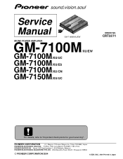
For details, refer to "Important check points for good servicing". Service Manual
GM-7100M/XU/EW
MONO POWER AMPLIFIER
GM-7100M/XU/EW
GM-7100M/XU/UC GM-7100M/XU/ES GM-7100M/XU/CN GM-7150M/XU/UC
ORDER NO.
PIONEER CORPORATION
4-1, Meguro 1-Chome, Meguro-ku, Tokyo 153...
Service Manual - Page 2

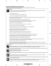
... the safety instructions described in solder and certain electrical parts contain chemicals which are not qualified to perform the repair of this manual. Improperly performed repairs can adversely affect the safety and reliability of California to cause cancer, birth defects or other regulations), and should not risk trying to do -it-yourselfer.
Health & Safety Code Section...
Service Manual - Page 3
...transit, the shipping mode should be finished with the procedures/instructions described in projection monitors, proper cleaning should be
installed before shipment. Soldering should be set to the original state after repairs.
When you solder while repairing, please be no damages. Lubricants, Glues, and Replacement parts
E
Use grease and adhesives that are marked with a suitable...
Service Manual - Page 4
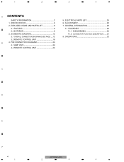
SPECIFICATIONS 5
2. PCB CONNECTION DIAGRAM 20
4.1 AMP UNIT 20
4.2 REMOTE CONTROL UNIT 24
5. 1
2
3
4
A CONTENTS
SAFETY INFORMATION 2
1. GENERAL INFORMATION 29
7.1 DIAGNOSIS 29 7.1.1 DISASSEMBLY 29 7.1.2 CONNECTOR FUNCTION DESCRIPTION ......31
8. EXPLODED VIEWS AND PARTS LIST 6
2.1 PACKING 6
2.2 EXTERIOR 8
3. SCHEMATIC DIAGRAM 12
3.1 OVERALL CONNECTION DIAGRAM(GUIDE ...
Service Manual - Page 5
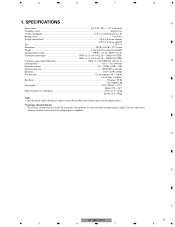
Use this unit when an audio signal is input.
SPECIFICATIONS
A
Power source ...14.4 V DC (10.8 - 15.1 V allowable)
...Maximum input level / impedance ...RCA: 6.5 V / 22 kΩ
Speaker: 26 V / 40 kΩ
Note:
C
• Specifications and the design are subject to possible modification without notice due to improvements.
*Average current drawn • The average current drawn is ...
Service Manual - Page 7
..., Spanish
CRD3923
English, Spanish
CRD3924
Arabic, Portuguese(B)
F
CRB2042
Traditional Chinese
GM-7100M/XU/EW
7
5
6
7
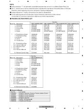
8 The > mark found on the product are not in this manual.
( In the case of lubricants or glue, follow the instructions in our Master Spare Parts List. -
Mark No. Description
GM-7150M/XU/UC
1 Cord Assy
CDE7736
2 Cord Assy
CDE7804
3 Screw Assy
CEA4836...
Service Manual - Page 9
...
Part No.
1 Screw 2 Screw 3 Screw 4 Screw 5 Screw
BBZ30P060FTC BBZ30P080FZK BBZ30P100FZK BBZ30P120FTC BSZ30P050FZK
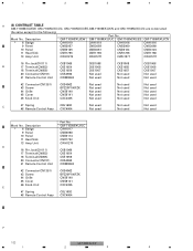
* 6 Badge 7 Screw 8 Case 9 Panel
10 Panel
See Contrast table(2) CBA1810 CNB3072 See Contrast table(2) See Contrast table(2)
11 Heat Sink 12 Spacer 13 Amp ... table(2) See Contrast table(2) See Contrast table(2) CNM9571
D
E
F
GM-7100M/XU/EW
9
5
6
7
8 5
6
7
8
-
Service Manual - Page 10
...
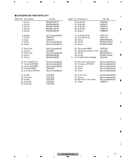
Part No. GM-7150M/XU/UC CAH1917 CNB3058 CNB3114 CNR1792 CWH1270
CKB1069 CKE1054 CKE1056 CKS4962 CWM9848
42 Connector(CN1351)
CKS4962
43 Screw
BPZ20P100FZK
44 Grille
CNS8140
45 Cover
CNS8141
46 Knob Unit
CXC4335
E
47 Spring 48 Remote Control Assy
CBL1692 CXC4064
F
10
GM-7100M/XU/EW
1
2
3
4 Mark No. Description
GM-7100M/XU/EW GM-7100M/XU/UC GM-7100M/XU/ES GM-7100M...
Service Manual - Page 12
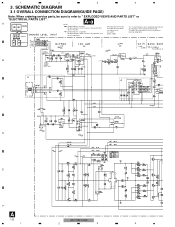
...diagram
A-a A-b Guide page
A-a
NOTE :
Symbol indicates a resistor.
Symbol indicates a capacitor.
Therefore, when replacing, be sure to refer to use parts of the part. A-a
A-b ...A
12
GM-7100M/XU/EW
1
2
3
4 SCHEMATIC DIAGRAM
3.1 OVERALL CONNECTION DIAGRAM(GUIDE PAGE)
Note: When ordering service parts, be sure to " EXPLODED VIEWS AND PARTS LIST" or
"ELECTRICAL PARTS LIST". ...
Service Manual - Page 20

... diagrams
Connector Capacitor
SIDE A
B
SIDE B
P.C.Board Chip Part
SPEAKER OUTPUT
SPEAKER OUTPUT
C
POWER SUPPLY
D
E
F
A
20 1
3 2 1
3 2 1
3 2 1
3 2 1
3 2 1
3 2 1
GM-7100M/XU/EW
2
3
4 1
2
3
4
4. PCB CONNECTION DIAGRAM
4.1 AMP UNIT
A
NOTE FOR PCB DIAGRAMS 1.The parts mounted on this PCB
A AMP UNIT
include all necessary parts for
respective destinations, be sure
to check...
Service Manual - Page 25
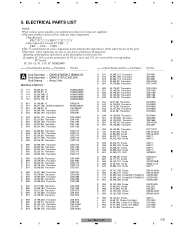
...111) IC NJM2068V
=====Circuit Symbol and No.===Part Name
Part No
A Unit Number : CWH1270(EW,7150M/UC) Unit Number : CWH1271(UC,ES,CN) Unit Name : Amp Unit
MISCELLANEOUS
IC 111 IC 112 IC ...µH T 901 (A,101,86) Transformer
CTH1326 CTT1123
F
GM-7100M/XU/EW
25
5
6
7
8 Example) IC 301 is on some component parts indicatesthe importance of the safety factor of the figures and others...
Service Manual - Page 28
E
F
28
GM-7100M/XU/EW
1
2
3
4 A
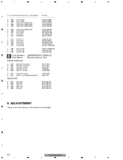
C ...C 993 (A,136,176) C 994 (A,130,176)
CEAT471M50(P45) CQHA102J2A CQHA102J2A
B Unit Number : CWM9848(EW,7150M/UC) Unit Name : Remote Control Unit
MISCELLANEOUS
Q 1351 (B,21,23) Transistor
Q 1352 (B,22,6) Transistor
C...
3
4
=====Circuit Symbol and No.===Part Name Part No.
ADJUSTMENT
There is no information to be shown in this chapter.
Service Manual - Page 29
...
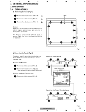
Removing the Case (Fig. 1)
A
1 Remove two black screws (M3 x 10). Take care not to secure the RCA Holder.)
Panel for the Power Terminal side
3
3
3
3
3
3
F
Fig. 2
GM-7100M/XU/EW
29
5
6
7
8 Case
2 Remove six white screws (M3 x 6).
3 Remove four black screws (M3 x 5).
2
2
2
Caution)
3
When you disassemble/re-assemble the Product
with it placed...
Service Manual - Page 30
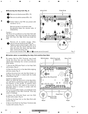
...black screws (M3 x 5). This may break the PCB.
2 1
Remove all of two panels. 1
2
3
4
Removing the Amp Unit (Fig. 3)
A
1 Remove six black screws (M3 x 10). 2 Remove six white screws (M3 x 12). Tighten ...screws. (Fig. 3)
F
6) Secure the Panel for the RCA side
Stud
Fig. 4
30
GM-7100M/XU/EW
1
2
3
4 Caution) The Amp Unit is M3 x 8 or
more into the two screw holes so as to 12.
2...
Service Manual - Page 32
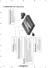
...level from 40 to 240 Hz. For instruction of connecting the bass boost remote control to...car stereo (standard output of 500 mV), set to the amplifier, see the "Connection Diagram" section.
When using with your car... Pioneer car stereo with this power amplifier is turned up , turn the gain control counter-clockwise. OPERATIONS (GM-7100M/XU/EW)
4
3
2
1 A 8. 4
3
2
1
GM-7100M/...
Pioneer GM-7150M Reviews
We have not received any reviews for Pioneer yet.