Service Manual
Page 1
PIONEER CORPORATION 4-1, Meguro 1-Chome, Meguro-ku, Tokyo 153-8654, Japan PIONEER ELECTRONICS (USA) INC. PIONEER EUROPE NV Haven 1087 Keetberglaan 1, 9120 Melsele, Belgium PIONEER ELECTRONICS ASIACENTRE PTE.LTD. 253 Alexandra Road, #04-01, Singapore 159936 C PIONEER CORPORATION 2004 K-ZZB. DEC. 2004 Printed in Japan Service Manual GM-7100M/XU/EW MONO POWER AMPLIFIER GM-7100M/XU/EW GM-7100M/XU/UC GM-7100M/XU/ES GM-7100M/XU/CN GM-7150M/XU/UC ORDER NO. CRT3371 For details, refer to "Important check points for good servicing". P.O.Box 1760, Long Beach, CA 90801-1760 U.S.A.
PIONEER CORPORATION 4-1, Meguro 1-Chome, Meguro-ku, Tokyo 153-8654, Japan PIONEER ELECTRONICS (USA) INC. PIONEER EUROPE NV Haven 1087 Keetberglaan 1, 9120 Melsele, Belgium PIONEER ELECTRONICS ASIACENTRE PTE.LTD. 253 Alexandra Road, #04-01, Singapore 159936 C PIONEER CORPORATION 2004 K-ZZB. DEC. 2004 Printed in Japan Service Manual GM-7100M/XU/EW MONO POWER AMPLIFIER GM-7100M/XU/EW GM-7100M/XU/UC GM-7100M/XU/ES GM-7100M/XU/CN GM-7150M/XU/UC ORDER NO. CRT3371 For details, refer to "Important check points for good servicing". P.O.Box 1760, Long Beach, CA 90801-1760 U.S.A.

Service Manual
Page 2
... to perform the repair of this product properly and safely, you are known to the state of the product and may void the warranty. Proposition 65 - Health & Safety Code Section 25249.6 - If you should conform to cause cancer, birth defects or other regulations), and should keep the safety during servicing by this manual. C D E F 2 GM-7100M/XU...
... to perform the repair of this product properly and safely, you are known to the state of the product and may void the warranty. Proposition 65 - Health & Safety Code Section 25249.6 - If you should conform to cause cancer, birth defects or other regulations), and should keep the safety during servicing by this manual. C D E F 2 GM-7100M/XU...
Service Manual
Page 3
... semi-broken wires, scratches, melting, etc. on secure D connections and suitable usage. Lubricants, Glues, and Replacement parts E Use grease and adhesives that there are no loose screws. 5 Make sure each connectors are no damages. Shipping mode and Shipping screws To protect products from damages or failures during transit, the shipping mode should be set to the specified substance. When you solder while repairing, please...
... semi-broken wires, scratches, melting, etc. on secure D connections and suitable usage. Lubricants, Glues, and Replacement parts E Use grease and adhesives that there are no loose screws. 5 Make sure each connectors are no damages. Shipping mode and Shipping screws To protect products from damages or failures during transit, the shipping mode should be set to the specified substance. When you solder while repairing, please...
Service Manual
Page 4
PCB CONNECTION DIAGRAM 20 4.1 AMP UNIT 20 4.2 REMOTE CONTROL UNIT 24 5. ELECTRICAL PARTS LIST 25 6. 1 2 3 4 A CONTENTS SAFETY INFORMATION 2 1. EXPLODED VIEWS AND PARTS LIST 6 2.1 PACKING 6 2.2 EXTERIOR 8 3. SCHEMATIC DIAGRAM 12 3.1 OVERALL CONNECTION DIAGRAM(GUIDE PAGE) ....12 3.2 REMOTE CONTROL UNIT 18 B 4. ADJUSTMENT 28 7. OPERATIONS 32 C D E F 4 GM-7100M/XU/EW 1 2 3 4 SPECIFICATIONS 5 2. GENERAL INFORMATION 29 7.1 DIAGNOSIS 29 7.1.1 DISASSEMBLY 29 7.1.2 CONNECTOR FUNCTION DESCRIPTION ......31 8.
PCB CONNECTION DIAGRAM 20 4.1 AMP UNIT 20 4.2 REMOTE CONTROL UNIT 24 5. ELECTRICAL PARTS LIST 25 6. 1 2 3 4 A CONTENTS SAFETY INFORMATION 2 1. EXPLODED VIEWS AND PARTS LIST 6 2.1 PACKING 6 2.2 EXTERIOR 8 3. SCHEMATIC DIAGRAM 12 3.1 OVERALL CONNECTION DIAGRAM(GUIDE PAGE) ....12 3.2 REMOTE CONTROL UNIT 18 B 4. ADJUSTMENT 28 7. OPERATIONS 32 C D E F 4 GM-7100M/XU/EW 1 2 3 4 SPECIFICATIONS 5 2. GENERAL INFORMATION 29 7.1 DIAGNOSIS 29 7.1.1 DISASSEMBLY 29 7.1.2 CONNECTOR FUNCTION DESCRIPTION ......31 8.
Service Manual
Page 5
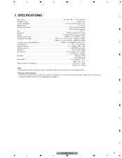
... ratio ...100 dB (IEC-A network) Distortion ...0.03 % (10 W, 120 Hz) Low pass filter ...Cut off frequency: 40 - 240 Hz Cut off slope: -12 dB/oct Bass Boost ...Frequency: 50 Hz Level: 0/6/9/12 dB Gain control ...RCA: 200 mV - 6.5 V Speaker: 0.8 - 26 V Maximum input level / impedance ...RCA: 6.5 V / 22 kΩ Speaker: 26 V / 40 kΩ Note: C • Specifications and the design are subject to possible modification without notice due to improvements...
... ratio ...100 dB (IEC-A network) Distortion ...0.03 % (10 W, 120 Hz) Low pass filter ...Cut off frequency: 40 - 240 Hz Cut off slope: -12 dB/oct Bass Boost ...Frequency: 50 Hz Level: 0/6/9/12 dB Gain control ...RCA: 200 mV - 6.5 V Speaker: 0.8 - 26 V Maximum input level / impedance ...RCA: 6.5 V / 22 kΩ Speaker: 26 V / 40 kΩ Note: C • Specifications and the design are subject to possible modification without notice due to improvements...
Service Manual
Page 6
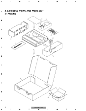
EXPLODED VIEWS AND PARTS LIST 2.1 PACKING B 8 1 C 11 3 6 5 54 7 2 12 8 D 9 E F 6 1 10 GM-7100M/XU/EW 2 3 4 1 2 3 4 A 2.
EXPLODED VIEWS AND PARTS LIST 2.1 PACKING B 8 1 C 11 3 6 5 54 7 2 12 8 D 9 E F 6 1 10 GM-7100M/XU/EW 2 3 4 1 2 3 4 A 2.
Service Manual
Page 7
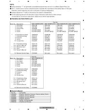
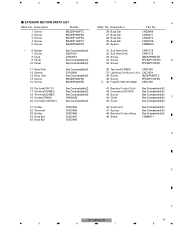
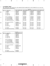
Therefore, when replacing, be sure to ∇ mark on some component parts indicates the importance of the safety factor of no amount instructions, apply as you think it appropriate.) - A - Description 1 Cord Assy 2 Cord Assy 3 Screw Assy 4 Screw 5 Screw Part No. Description GM-7150M/XU/UC 1 Cord Assy CDE7736 2 Cord Assy CDE7804 3 Screw Assy CEA4836 4 Screw BYC30P100FZK D 5 Screw BYC40P180FZK * 6 Polyethylene Sheet 7 Polyethylene Bag 8 Protector 9 Carton...
Therefore, when replacing, be sure to ∇ mark on some component parts indicates the importance of the safety factor of no amount instructions, apply as you think it appropriate.) - A - Description 1 Cord Assy 2 Cord Assy 3 Screw Assy 4 Screw 5 Screw Part No. Description GM-7150M/XU/UC 1 Cord Assy CDE7736 2 Cord Assy CDE7804 3 Screw Assy CEA4836 4 Screw BYC30P100FZK D 5 Screw BYC40P180FZK * 6 Polyethylene Sheet 7 Polyethylene Bag 8 Protector 9 Carton...
Service Manual
Page 9
... 29 Buss Bar 30 Spacer A Part No. CND2469 CND2471 CND2472 CND2729 CNM9570 31 Sub Heat Sink 32 Sub Heat Sink 33 Screw 34 Screw 35 Screw CNR1778 CNR1779 IMS30P050FZK PPZ30P100FSN B PPZ30P100FZK 36 Terminal(CN850) VNF1084 37 Lighting Conductor Unit CXC4334 38 Screw IBZ30P060FTC 39 Screw PPZ30P100FZK > 40 Fuse(FU100,101)(30A) CEK1330 41 Remote Control Unit See Contrast table(2) 42 Connector(CN1351) See Contrast table(2) 43...
... 29 Buss Bar 30 Spacer A Part No. CND2469 CND2471 CND2472 CND2729 CNM9570 31 Sub Heat Sink 32 Sub Heat Sink 33 Screw 34 Screw 35 Screw CNR1778 CNR1779 IMS30P050FZK PPZ30P100FSN B PPZ30P100FZK 36 Terminal(CN850) VNF1084 37 Lighting Conductor Unit CXC4334 38 Screw IBZ30P060FTC 39 Screw PPZ30P100FZK > 40 Fuse(FU100,101)(30A) CEK1330 41 Remote Control Unit See Contrast table(2) 42 Connector(CN1351) See Contrast table(2) 43...
Service Manual
Page 10
... Panel 11 Heat Sink 13 Amp Unit D 16 Pin Jack(CN111) 17 Terminal(CN853) 18 Terminal(CN855) 20 Connector(CN701) 41 Remote Control Unit Part No. GM-7150M/XU/UC CAH1917 CNB3058 CNB3114 CNR1792 CWH1270 CKB1069 CKE1054 CKE1056 CKS4962 CWM9848 42 Connector(CN1351) CKS4962 43 Screw BPZ20P100FZK 44 Grille CNS8140 45 Cover CNS8141 46 Knob Unit CXC4335 E 47 Spring 48 Remote Control Assy CBL1692 CXC4064 F 10...
... Panel 11 Heat Sink 13 Amp Unit D 16 Pin Jack(CN111) 17 Terminal(CN853) 18 Terminal(CN855) 20 Connector(CN701) 41 Remote Control Unit Part No. GM-7150M/XU/UC CAH1917 CNB3058 CNB3114 CNR1792 CWH1270 CKB1069 CKE1054 CKE1056 CKS4962 CWM9848 42 Connector(CN1351) CKS4962 43 Screw BPZ20P100FZK 44 Grille CNS8140 45 Cover CNS8141 46 Knob Unit CXC4335 E 47 Spring 48 Remote Control Assy CBL1692 CXC4064 F 10...
Service Manual
Page 12
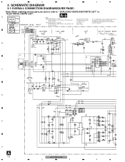
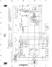
... size A-a A-b SCH diagram A-a A-b Guide page A-a NOTE : Symbol indicates a resistor. A-a A-b Detailed page B 0dB +18.5dBs (BB ON INPUT MAX) 0dB +18.3dBs +17.5dBs LPF 0dB -1.7dB ~ -32.0dB 0dB or +12dB or +6dB ( or +9 +17.5dBs -15dBs B GAIN A BASS BOOST A B CN1351 C -0.8dB D E F A 12 GM-7100M/XU/EW 1 2 3 4 1 2 3 4 3. SCHEMATIC DIAGRAM 3.1 OVERALL CONNECTION DIAGRAM(GUIDE PAGE) Note: When ordering service parts, be sure to " EXPLODED VIEWS AND PARTS LIST" or "ELECTRICAL PARTS LIST". No...
... size A-a A-b SCH diagram A-a A-b Guide page A-a NOTE : Symbol indicates a resistor. A-a A-b Detailed page B 0dB +18.5dBs (BB ON INPUT MAX) 0dB +18.3dBs +17.5dBs LPF 0dB -1.7dB ~ -32.0dB 0dB or +12dB or +6dB ( or +9 +17.5dBs -15dBs B GAIN A BASS BOOST A B CN1351 C -0.8dB D E F A 12 GM-7100M/XU/EW 1 2 3 4 1 2 3 4 3. SCHEMATIC DIAGRAM 3.1 OVERALL CONNECTION DIAGRAM(GUIDE PAGE) Note: When ordering service parts, be sure to " EXPLODED VIEWS AND PARTS LIST" or "ELECTRICAL PARTS LIST". No...
Service Manual
Page 14
.... Therefore, when replacing, be sure to use parts of the part. 1 A-b A B C D E F A-a 14 1 2 2 A-a A-b NOTE : Symbol indicates a resistor. No differentiation is made between chip capacitors and discrete capacitors. ← ← Decimal points for resistor and capacitor fixed values are expressed ...on some component parts indicates the importance of the safety factor of identical designation. 0dB +18.5dBs (BB ON INPUT MAX) A 0dB +18.3dBs +17.5dBs 0dB LPF A -1.7dB ~ -32.0dB 0dB or +12dB or +6dB ( or +9dB) +17.5dBs -15dBs -2.6dBs B GAIN BASS BOOST GM-7100M/XU/EW...
.... Therefore, when replacing, be sure to use parts of the part. 1 A-b A B C D E F A-a 14 1 2 2 A-a A-b NOTE : Symbol indicates a resistor. No differentiation is made between chip capacitors and discrete capacitors. ← ← Decimal points for resistor and capacitor fixed values are expressed ...on some component parts indicates the importance of the safety factor of identical designation. 0dB +18.5dBs (BB ON INPUT MAX) A 0dB +18.3dBs +17.5dBs 0dB LPF A -1.7dB ~ -32.0dB 0dB or +12dB or +6dB ( or +9dB) +17.5dBs -15dBs -2.6dBs B GAIN BASS BOOST GM-7100M/XU/EW...

Service Manual
Page 20
PCB CONNECTION DIAGRAM 4.1 AMP UNIT A NOTE FOR PCB DIAGRAMS 1.The parts mounted on this PCB A AMP UNIT include all necessary parts for respective destinations, be sure to check with the schematic dia- 1 2 3 4 4. For further information for several destination. gram. 2.Viewpoint of PCB diagrams Connector Capacitor SIDE A B SIDE B P.C.Board Chip Part SPEAKER OUTPUT SPEAKER OUTPUT C POWER SUPPLY D E F A 20 1 3 2 1 3 2 1 3 2 1 3 2 1 3 2 1 3 2 1 GM-7100M/XU/EW 2 3 4
PCB CONNECTION DIAGRAM 4.1 AMP UNIT A NOTE FOR PCB DIAGRAMS 1.The parts mounted on this PCB A AMP UNIT include all necessary parts for respective destinations, be sure to check with the schematic dia- 1 2 3 4 4. For further information for several destination. gram. 2.Viewpoint of PCB diagrams Connector Capacitor SIDE A B SIDE B P.C.Board Chip Part SPEAKER OUTPUT SPEAKER OUTPUT C POWER SUPPLY D E F A 20 1 3 2 1 3 2 1 3 2 1 3 2 1 3 2 1 3 2 1 GM-7100M/XU/EW 2 3 4
Service Manual
Page 25
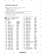
..., when replacing, be sure to being not supplied. B IC 301 (A, 91, 111) IC NJM2068V =====Circuit Symbol and No.===Part Name Part No A Unit Number : CWH1270(EW,7150M/UC) Unit Number : CWH1271(UC,ES,CN) Unit Name : Amp Unit MISCELLANEOUS IC...GM-7100M/XU/EW 25 5 6 7 8 Example) IC 301 is on some component parts indicatesthe importance of the safety factor of the corresponding PC board. The part numbers shown below indicate chip components. Meaning of identical designation. ELECTRICAL PARTS LIST A NOTE: Parts whose parts numbers are omitted are subject to use parts...
..., when replacing, be sure to being not supplied. B IC 301 (A, 91, 111) IC NJM2068V =====Circuit Symbol and No.===Part Name Part No A Unit Number : CWH1270(EW,7150M/UC) Unit Number : CWH1271(UC,ES,CN) Unit Name : Amp Unit MISCELLANEOUS IC...GM-7100M/XU/EW 25 5 6 7 8 Example) IC 301 is on some component parts indicatesthe importance of the safety factor of the corresponding PC board. The part numbers shown below indicate chip components. Meaning of identical designation. ELECTRICAL PARTS LIST A NOTE: Parts whose parts numbers are omitted are subject to use parts...
Service Manual
Page 26
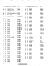
...Switch (UC,ES,CN)(BASS BOOST) CCX1013 CCX1013 CCX1064 CSH1029 S 901 VR 151 VR 201 > FU 100 > FU 101 (A,9,200) Switch(BFC) HSH-156 (A,309,119) Volume 20kΩ(E)(LPF) CCS1266 (A,311,154) Volume 10kΩ(A)(GAIN) CCS1241 (A,20,45) Fuse 30A CEK1330 (A,20,68) Fuse...,136) R 557 (B,236,92) R 558 (B,226,133) R 559 (B,231,92) RS1/16S103J RS1/16S103J RS1/16S473J RS1/16S473J RS1/16S331J =====Circuit Symbol and No.===Part Name R 560 (B,225,143) R 561 (B,233,92) R 562 (B,225,145) R 563 (B,222,87) R 564 (B,216,139) R ... RD1/4PU222J RS1/16S1R0J RS1/16S104J 26 GM-7100M/XU/EW 1 2 3 4
...Switch (UC,ES,CN)(BASS BOOST) CCX1013 CCX1013 CCX1064 CSH1029 S 901 VR 151 VR 201 > FU 100 > FU 101 (A,9,200) Switch(BFC) HSH-156 (A,309,119) Volume 20kΩ(E)(LPF) CCS1266 (A,311,154) Volume 10kΩ(A)(GAIN) CCS1241 (A,20,45) Fuse 30A CEK1330 (A,20,68) Fuse...,136) R 557 (B,236,92) R 558 (B,226,133) R 559 (B,231,92) RS1/16S103J RS1/16S103J RS1/16S473J RS1/16S473J RS1/16S331J =====Circuit Symbol and No.===Part Name R 560 (B,225,143) R 561 (B,233,92) R 562 (B,225,145) R 563 (B,222,87) R 564 (B,216,139) R ... RD1/4PU222J RS1/16S1R0J RS1/16S104J 26 GM-7100M/XU/EW 1 2 3 4
Service Manual
Page 28
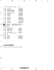
...B Unit Number : CWM9848(EW,7150M/UC) Unit Name : Remote Control Unit MISCELLANEOUS Q 1351 (B,21,23) Transistor Q 1352 (B,22,6) Transistor C D 1351 (B,12,25) Diode D 1352 (B,16,6) Diode D 1366 (B,21,11) Diode DTC114EU DTC114EU DAN202U DAN202U UDZS16(B) D 1367 (B,29,16) Diode S 1351 (A,6,11) Switch(BASS BOOST) ...UDZS16(B) CSD1128 RESISTORS R 1351 R 1352 R 1353 R 1354 R 1359 (B,15,16) (B,18,18) (B,31,21) (B,31,16) (B,16,8) RS1/16S103J RS1/16S102J RS1/16S103J RS1/16S102J RS1/16S102J D 6. 1 2 3 4 =====Circuit Symbol and No.===Part Name Part No. ADJUSTMENT...
...B Unit Number : CWM9848(EW,7150M/UC) Unit Name : Remote Control Unit MISCELLANEOUS Q 1351 (B,21,23) Transistor Q 1352 (B,22,6) Transistor C D 1351 (B,12,25) Diode D 1352 (B,16,6) Diode D 1366 (B,21,11) Diode DTC114EU DTC114EU DAN202U DAN202U UDZS16(B) D 1367 (B,29,16) Diode S 1351 (A,6,11) Switch(BASS BOOST) ...UDZS16(B) CSD1128 RESISTORS R 1351 R 1352 R 1353 R 1354 R 1359 (B,15,16) (B,18,18) (B,31,21) (B,31,16) (B,16,8) RS1/16S103J RS1/16S102J RS1/16S103J RS1/16S102J RS1/16S102J D 6. 1 2 3 4 =====Circuit Symbol and No.===Part Name Part No. ADJUSTMENT...
Service Manual
Page 29
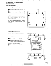
... and the other for the Power Terminal side 3 3 3 3 3 3 F Fig. 2 GM-7100M/XU/EW 29 5 6 7 8 Panel for the RCA side 1 1 1 1 22 RCA Terminal (CN111) C Fig. 1 1 D 1 E Panel for the Power Terminal side. Panel for the RCA side 1 Remove six black screws (M3 x 8). 2 Remove two black screws (M3 x 5). (They are used to secure the RCA Holder.) Panel for the Power Terminal side 3 Remove six black screws (M3 x 8). GENERAL INFORMATION 7.1 DIAGNOSIS 7.1.1 DISASSEMBLY Removing...
... and the other for the Power Terminal side 3 3 3 3 3 3 F Fig. 2 GM-7100M/XU/EW 29 5 6 7 8 Panel for the RCA side 1 1 1 1 22 RCA Terminal (CN111) C Fig. 1 1 D 1 E Panel for the Power Terminal side. Panel for the RCA side 1 Remove six black screws (M3 x 8). 2 Remove two black screws (M3 x 5). (They are used to secure the RCA Holder.) Panel for the Power Terminal side 3 Remove six black screws (M3 x 8). GENERAL INFORMATION 7.1 DIAGNOSIS 7.1.1 DISASSEMBLY Removing...
Service Manual
Page 30
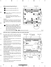
... silicon grease. Tighten screws whose length is adhered on the Heat Sink with screws. (Fig. 3) F 6) Secure the Panel for the RCA side Stud Fig. 4 30 GM-7100M/XU/EW 1 2 3 4 This means forcibly removing the Amp Unit from the Heat Sink may result in place with numbers 1 to determine the direction of B disassembly. 1 2 3 4 Removing the Amp Unit (Fig. 3) A 1 Remove six black screws (M3 x 10...
... silicon grease. Tighten screws whose length is adhered on the Heat Sink with screws. (Fig. 3) F 6) Secure the Panel for the RCA side Stud Fig. 4 30 GM-7100M/XU/EW 1 2 3 4 This means forcibly removing the Amp Unit from the Heat Sink may result in place with numbers 1 to determine the direction of B disassembly. 1 2 3 4 Removing the Amp Unit (Fig. 3) A 1 Remove six black screws (M3 x 10...
Service Manual
Page 32
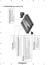
... Pioneer car stereo with an RCA equipped car stereo (standard output of connecting the bass boost remote control to the amplifier, see the "Connection Diagram" section. When using a small standard tip screwdriver. D C B BFC (Beat Frequency Control) Switch If you hear too much noise when using the speaker input terminals, turn the gain control counter-clockwise. If the sound distorts when the volume is turned up , turn gain control on . For instruction of 500 mV), set to 240 Hz. output of the power amplifier clockwise. LPF (Low-Pass-Filter) Cut Off Frequency Control...
... Pioneer car stereo with an RCA equipped car stereo (standard output of connecting the bass boost remote control to the amplifier, see the "Connection Diagram" section. When using a small standard tip screwdriver. D C B BFC (Beat Frequency Control) Switch If you hear too much noise when using the speaker input terminals, turn the gain control counter-clockwise. If the sound distorts when the volume is turned up , turn gain control on . For instruction of 500 mV), set to 240 Hz. output of the power amplifier clockwise. LPF (Low-Pass-Filter) Cut Off Frequency Control...


