Pioneer GM-X554 Support and Manuals
Get Help and Manuals for this Pioneer item
View All Support Options Below
Free Pioneer GM-X554 manuals!
Problems with Pioneer GM-X554?
Ask a Question
Free Pioneer GM-X554 manuals!
Problems with Pioneer GM-X554?
Ask a Question
Popular Pioneer GM-X554 Manual Pages
Service Manual - Page 1

Service GM-X554/X1R/EW
Manual
BRIDGEABLE FOUR-CHANNEL POWER AMPLIFIER
GM-X554
GM-X554 X1R/EW GM-X554 X1R/ES
ORDER NO. CRT2613
X1R/UC
CONTENTS
1. OPERATIONS AND SPECIFICATIONS 21
PIONEER CORPORATION
4-1, Meguro 1-Chome, Meguro-ku, Tokyo 153-8654, Japan
PIONEER ELECTRONICS SERVICE INC. P.O.Box 1760, Long Beach, CA 90801-1760 U.S.A.
SAFETY INFORMATION 2 2. PCB CONNECTION DIAGRAM 12 ...
Service Manual - Page 2

GM-X554/X1R/UC CAUTION This service manual is not meant for qualified service technicians; it -yourselfer. EXPLODED VIEWS AND PARTS LIST
2.1 PACKING
2 Health & Safety Code Section 25249.6 - you are known to the state of California to properly and safely repair complex products such as those covered by this product properly and safely; Qualified technicians have the necessary test...
Service Manual - Page 3

..., French English, Spanish, German, French, Italian, Dutch English, Spanish Portuguese(B), Arabic
3 Screws adjacent to ∇ mark on the product are not in our Master Spare Parts List. - GM-X554
NOTE: - Parts marked by "*" are generally unavailable because they are used for disassembly.
- Owner's Manual Model
GM-X554/X1R/UC GM-X554/X1R/EW
GM-X554/X1R/ES
Part No.
Service Manual - Page 5

... HKE0020
Mark No.
Description
GM-X554/X1R/UC
GM-X554/X1R/EW
GM-X554/X1R/ES
8 Panel
HNB0128
HNB0147
HNB0128
10 Panel
HNB0136
HNB0142
HNB0136
12 Heat Sink
HNR0181
HNR0187
HNR0181
15 Amp Unit
HWH0148
HWH0147
HWH0149
5
Description 21 Connector(CN301) 22 Clip 23 Holder 24 Screw 25 Light Pipe Unit
26 Screw
Part No. Mark No. Description...
Service Manual - Page 6
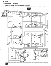
... ordering service parts, be sure to refer to "EXPLODED VIEWS AND PARTS LIST" or "ELECTRICAL PARTS
LIST". 1
2
3
4
GM-X554
3. A
A-a
Large size
A-a
A-b
SCH diagram
A-a A-b Guide page
A-a
A-b Detailed page
ISOLATOR GAIN = 1
HP/LP FILTER 40 - 120Hz 12dB/OCTAVE
HP/LP FILTER
OUTPUT L
OUTPUT R
B
V V
INPUT SELECT
C
±25V REGULATOR
DC/DC CONVERTER
D
A 6
1
2
3
(EW,ES model...
Service Manual - Page 8

4
3
2
1
8 A-a
D
OUTPUT L
ISOLATOR GAIN = 1
OUTPUT R
INPUT SELECT
C
B
A-a A-b
HP/LP FILTER 40 - 120Hz 12dB/OCTAVE
HP/LP FILTER
V V
A
GM-X554
4
3
2
1
Service Manual - Page 12

..., be sure to check with the schematic diagram. 2. For further information for several destination. Viewpoint of PCB diagrams
Connector Capacitor
SIDE A
A AMP UNIT
GAIN
LPF/ HPF SELECT
FREQ
P.C.Board Chip Part B
SIDE B
INPUT SELECT
INPUT B LR
INPUT A
OUTPUT
C
FREQ
LPF/ HPF SELECT
GAIN
D
A 12
1
2
3
4 1
2
3
4
GM-X554
4. PCB CONNECTION DIAGRAM
4.1 AMP UNIT
NOTE FOR PCB...
Service Manual - Page 17

GM-X554
=====Circuit Symbol and No.===Part Name
L 851 Ferri-Inductor L 852 Ferri-Inductor L 853 Ferri-Inductor L 854 Ferri-Inductor T 601 Transformer
TH 601 TH 602 TH 603 S 101 S 102
Thermistor Thermistor Thermistor Switch(LPF/HPF SELECT) Switch(LPF/HPF SELECT)
S 601 S 851 VR 121 VR 122 VR 201
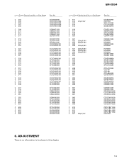
Switch(BFC)(EW,ES model...211 R 212 R 213 R 214
Part No
CTF1007 CTF1007 CTF1007 CTF1007 HTT0014
...
Service Manual - Page 19
GM-X554
=====Circuit Symbol and No.===Part Name
C 304 C 305 C 306 C 307 C 308
C 309 C 310 C 311 C 312 C 317
C 318... C 863 C 864 C 865 C 866
C 875 C 876 C 877 C 878 C 901 220µF/10V
Part No
CEAS220M50 CCH1183 CFTLA103J50 CFTLA103J50 CEAS100M16
CEAS221M10 CQMA102J50 CFTLA105J50 CEAS470M50 CQMA472J50
CQMA472J50 HCH0005 HCH0005 CQMA102J50 HCH0006
HCH0006 HCH0006 HCH0006 CEAS471M35 CEAS471M35...
Service Manual - Page 20

... screws. Remove the three screws and then remove the Case. Removing the Amp Unit (Fig.2) Remove the twenty-four screws. Case
Panel
Fig.1
Amp Unit
Fig.2
20 Remove the two screws. Remove the twelve screws and then remove the Amp Unit. GM-X554
7. Removing the Case and the Panel (Fig.1) Remove the four screws.
Remove...
Service Manual - Page 21

8. OPERATIONS AND SPECIFICATIONS
8.1 OPERATIONS
- GM-X554/X1R/EW
GM-X554
21
Service Manual - Page 22

...car stereo to the Pioneer amplifier. Cut Off Frequency Control
If the LPF/HPF select switch is not necessary for the speakers you only use one input plug, set to LPF or HPF, you hear a beat while listening to an MW/LW broadcast with your car...GM-X554
22
Setting the Unit
Gain Control
Adjusting the gain controls A and B will help match the output of 4 V or more, adjust level to match the car...
Service Manual - Page 23

... all other connections at the amplifier, connect the battery wire terminal of the amplifier to the positive (+) terminal of the car stereo (SYSTEM REMOTE CONTROL).
The female terminal can be connected to the power terminal through the ignition switch.
23 RCA input
Connecting wires with RCA pin plugs (sold separately). GM-X554
RCA output jack
RCA input...
Service Manual - Page 24

...) Fuse ...20 A x 2 Dimensions 279 (W) x 58 (H) x 324 (D) mm
11 (W) x 2-1/4 (H) x 12-3/4 (D) in] Weight 4.8 kg (10.6 lbs) (Leads for wiring not included) Maximum power output 100 W x 4 / 240 W x 2 Continuous power output 50 W x 4 (at 14.4 V, 4 Ω, 20 - 20,000 Hz, 0.08...amplifiers.
- GM-X554
8.2 SPECIFICATIONS
- Use this value when working out total current drawn by multiple power...
Service Manual - Page 25

...: • Specifications and the design are subject to possible modification without notice due to
improvements. *Average current drawn • The average current drawn is input. Use this value when working out total current drawn by this unit when an
audio signal is nearly the maximum current drawn by multiple power amplifiers.
- GM-X554
25
Pioneer GM-X554 Reviews
We have not received any reviews for Pioneer yet.