
Service Manual
Page 1
CRT2613 X1R/UC CONTENTS 1. SCHEMATIC DIAGRAM 6 4. GENERAL INFORMATION 20 7.1 DISASSEMBLY 20 8. OPERATIONS AND SPECIFICATIONS 21 PIONEER CORPORATION 4-1, Meguro 1-Chome, Meguro-ku, Tokyo 153-8654, Japan PIONEER ELECTRONICS SERVICE INC. NOV. 2000 Printed in Japan ADJUSTMENT 19 7. PIONEER EUROPE N.V. PCB CONNECTION DIAGRAM 12 5. P.O.Box 1760, Long Beach, CA 90801-1760 U.S.A. Service GM-X554/X1R/EW Manual BRIDGEABLE FOUR-CHANNEL POWER AMPLIFIER GM-X554 GM-X554 X1R/EW GM-X554 X1R/ES ORDER NO. SAFETY INFORMATION 2 2. Haven...
CRT2613 X1R/UC CONTENTS 1. SCHEMATIC DIAGRAM 6 4. GENERAL INFORMATION 20 7.1 DISASSEMBLY 20 8. OPERATIONS AND SPECIFICATIONS 21 PIONEER CORPORATION 4-1, Meguro 1-Chome, Meguro-ku, Tokyo 153-8654, Japan PIONEER ELECTRONICS SERVICE INC. NOV. 2000 Printed in Japan ADJUSTMENT 19 7. PIONEER EUROPE N.V. PCB CONNECTION DIAGRAM 12 5. P.O.Box 1760, Long Beach, CA 90801-1760 U.S.A. Service GM-X554/X1R/EW Manual BRIDGEABLE FOUR-CHANNEL POWER AMPLIFIER GM-X554 GM-X554 X1R/EW GM-X554 X1R/ES ORDER NO. SAFETY INFORMATION 2 2. Haven...

Service Manual
Page 2
... properly and safely; SAFETY INFORMATION - GM-X554/X1R/UC CAUTION This service manual is not meant for qualified service technicians; If you should not risk trying to cause cancer, birth defects or other reproductive harm. Proposition 65 2. Improperly performed repairs can adversely affect the safety and reliability of this manual. Health & Safety Code Section 25249.6 - you are known...
... properly and safely; SAFETY INFORMATION - GM-X554/X1R/UC CAUTION This service manual is not meant for qualified service technicians; If you should not risk trying to cause cancer, birth defects or other reproductive harm. Proposition 65 2. Improperly performed repairs can adversely affect the safety and reliability of this manual. Health & Safety Code Section 25249.6 - you are known...

Service Manual
Page 3
... HHL0281 HHP0107 HEG0011 HEG0022 HHG0281 HHL0281 HHP0107 8 Cover HNS0101 HNS0101 HNS0101 - Owner's Manual Model GM-X554/X1R/UC GM-X554/X1R/EW GM-X554/X1R/ES Part No. PACKING SECTION PARTS LIST Mark No. GM-X554 NOTE: - GM-X554/X1R/EW HRY1157 HRD0159 Not used Not used BYC40P180FZK GM-X554/X1R/ES Not used HRD0168 HRD0174 Not used ARY1048 BYC40P180FZK Part No. Screws adjacent to ∇ mark on the product are not in our...
... HHL0281 HHP0107 HEG0011 HEG0022 HHG0281 HHL0281 HHP0107 8 Cover HNS0101 HNS0101 HNS0101 - Owner's Manual Model GM-X554/X1R/UC GM-X554/X1R/EW GM-X554/X1R/ES Part No. PACKING SECTION PARTS LIST Mark No. GM-X554 NOTE: - GM-X554/X1R/EW HRY1157 HRD0159 Not used Not used BYC40P180FZK GM-X554/X1R/ES Not used HRD0168 HRD0174 Not used ARY1048 BYC40P180FZK Part No. Screws adjacent to ∇ mark on the product are not in our...

Service Manual
Page 5
... Amp Unit HNC0080 See Contrast table(2) HNS0101 HNV0016 See Contrast table(2) 16 Terminal(CN604) 17 Fuse(20A) 18 Pin Jack(CN852) 19 Pin Jack(CN851) 20 Terminal(CN601) CKF1059 HEK0020 HKB0002 HKB0006 HKE0020 Mark No. Description 21 Connector(CN301) 22 Clip 23 Holder 24 Screw 25 Light Pipe Unit 26 Screw Part No. Mark No. GM-X554 (1) EXTERIOR SECTION PARTS LIST Mark No. Description 1 Screw 2 Screw 3 Screw 4 Screw 5 Screw(M3x12) Part...
... Amp Unit HNC0080 See Contrast table(2) HNS0101 HNV0016 See Contrast table(2) 16 Terminal(CN604) 17 Fuse(20A) 18 Pin Jack(CN852) 19 Pin Jack(CN851) 20 Terminal(CN601) CKF1059 HEK0020 HKB0002 HKB0006 HKE0020 Mark No. Description 21 Connector(CN301) 22 Clip 23 Holder 24 Screw 25 Light Pipe Unit 26 Screw Part No. Mark No. GM-X554 (1) EXTERIOR SECTION PARTS LIST Mark No. Description 1 Screw 2 Screw 3 Screw 4 Screw 5 Screw(M3x12) Part...
Service Manual
Page 6
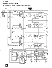
SCHEMATIC DIAGRAM 3.1 OVERALL CONNECTION DIAGRAM(GUIDE PAGE) Note: When ordering service parts, be sure to refer to "EXPLODED VIEWS AND PARTS LIST" or "ELECTRICAL PARTS LIST". A A-a Large size A-a A-b SCH diagram A-a A-b Guide page A-a A-b Detailed page ISOLATOR GAIN = 1 HP/LP FILTER 40 - 120Hz 12dB/OCTAVE HP/LP FILTER OUTPUT L OUTPUT R B V V INPUT SELECT C ±25V REGULATOR DC/DC CONVERTER D A 6 1 2 3 (EW,ES model) BFC 4 1 2 3 4 GM-X554 3.
SCHEMATIC DIAGRAM 3.1 OVERALL CONNECTION DIAGRAM(GUIDE PAGE) Note: When ordering service parts, be sure to refer to "EXPLODED VIEWS AND PARTS LIST" or "ELECTRICAL PARTS LIST". A A-a Large size A-a A-b SCH diagram A-a A-b Guide page A-a A-b Detailed page ISOLATOR GAIN = 1 HP/LP FILTER 40 - 120Hz 12dB/OCTAVE HP/LP FILTER OUTPUT L OUTPUT R B V V INPUT SELECT C ±25V REGULATOR DC/DC CONVERTER D A 6 1 2 3 (EW,ES model) BFC 4 1 2 3 4 GM-X554 3.

Service Manual
Page 8
4 3 2 1 8 A-a D OUTPUT L ISOLATOR GAIN = 1 OUTPUT R INPUT SELECT C B A-a A-b HP/LP FILTER 40 - 120Hz 12dB/OCTAVE HP/LP FILTER V V A GM-X554 4 3 2 1
4 3 2 1 8 A-a D OUTPUT L ISOLATOR GAIN = 1 OUTPUT R INPUT SELECT C B A-a A-b HP/LP FILTER 40 - 120Hz 12dB/OCTAVE HP/LP FILTER V V A GM-X554 4 3 2 1

Service Manual
Page 12
The parts mounted on this PCB include all necessary parts for respective destinations, be sure to check with the schematic diagram. 2. PCB CONNECTION DIAGRAM 4.1 AMP UNIT NOTE FOR PCB DIAGRAMS A 1. 1 2 3 4 GM-X554 4. Viewpoint of PCB diagrams Connector Capacitor SIDE A A AMP UNIT GAIN LPF/ HPF SELECT FREQ P.C.Board Chip Part B SIDE B INPUT SELECT INPUT B LR INPUT A OUTPUT C FREQ LPF/ HPF SELECT GAIN D A 12 1 2 3 4 For further information for several destination.
The parts mounted on this PCB include all necessary parts for respective destinations, be sure to check with the schematic diagram. 2. PCB CONNECTION DIAGRAM 4.1 AMP UNIT NOTE FOR PCB DIAGRAMS A 1. 1 2 3 4 GM-X554 4. Viewpoint of PCB diagrams Connector Capacitor SIDE A A AMP UNIT GAIN LPF/ HPF SELECT FREQ P.C.Board Chip Part B SIDE B INPUT SELECT INPUT B LR INPUT A OUTPUT C FREQ LPF/ HPF SELECT GAIN D A 12 1 2 3 4 For further information for several destination.

Service Manual
Page 16
The part numbers shown below indicate chip components. Parts whose parts numbers are omitted are subject to being not supplied. - Chip Resistor RS1/_S___J,RS1/__S___J Chip Capacitor (except for CQS.....) CKS....., CCS....., CSZS..... =====Circuit Symbol and No.===Part Name Part No A Unit Number : HWH0148(GM-X554/X1R/UC) : HWH0147(GM-X554/X1R/EW) : HWH0149(GM-X554/X1R/ES) Unit Name : Amp Unit MISCELLANEOUS IC...B2) 1SS133 1SS133 1SS133 FML22R FML22S HZS16L(1) HZS16L(1) ERA15-02VH ERA15-02VH 1SS133 1SS133 1SS133 1SS133 1SS133 SML210LT(LMN) GM-X554 5. ELECTRICAL PARTS LIST NOTE: -
The part numbers shown below indicate chip components. Parts whose parts numbers are omitted are subject to being not supplied. - Chip Resistor RS1/_S___J,RS1/__S___J Chip Capacitor (except for CQS.....) CKS....., CCS....., CSZS..... =====Circuit Symbol and No.===Part Name Part No A Unit Number : HWH0148(GM-X554/X1R/UC) : HWH0147(GM-X554/X1R/EW) : HWH0149(GM-X554/X1R/ES) Unit Name : Amp Unit MISCELLANEOUS IC...B2) 1SS133 1SS133 1SS133 FML22R FML22S HZS16L(1) HZS16L(1) ERA15-02VH ERA15-02VH 1SS133 1SS133 1SS133 1SS133 1SS133 SML210LT(LMN) GM-X554 5. ELECTRICAL PARTS LIST NOTE: -

Service Manual
Page 17
GM-X554 =====Circuit Symbol and No.===Part Name L 851 Ferri-Inductor L 852 Ferri-Inductor L 853 Ferri-Inductor L 854 Ferri-Inductor T 601 Transformer TH 601 TH 602 TH 603 S 101 S 102 Thermistor Thermistor Thermistor Switch(LPF/HPF SELECT) Switch(LPF/HPF SELECT) S 601 S 851 VR 121 VR 122 VR 201 Switch(BFC)(EW,ES model) Switch(INPUT... SELECT) 20kΩ(E) 20kΩ(E) 10kΩ(A) VR 202 10kΩ(A) Fuse 20A RESISTORS R 101 R ...
GM-X554 =====Circuit Symbol and No.===Part Name L 851 Ferri-Inductor L 852 Ferri-Inductor L 853 Ferri-Inductor L 854 Ferri-Inductor T 601 Transformer TH 601 TH 602 TH 603 S 101 S 102 Thermistor Thermistor Thermistor Switch(LPF/HPF SELECT) Switch(LPF/HPF SELECT) S 601 S 851 VR 121 VR 122 VR 201 Switch(BFC)(EW,ES model) Switch(INPUT... SELECT) 20kΩ(E) 20kΩ(E) 10kΩ(A) VR 202 10kΩ(A) Fuse 20A RESISTORS R 101 R ...
Service Manual
Page 19
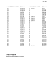
ADJUSTMENT There is no information to be shown in this chapter. 19 GM-X554 =====Circuit Symbol and No.===Part Name C 304 C 305 C 306 C 307 C 308 C 309 C 310 C 311 C 312 C 317 C 318 C 319 C 320 C 321 C 322 C 323 C 324 C... CCCCH100J100 CCCCH100J100 CCCCH100J100 CCCCH100J100 CCCCH100J100 CFTLA333J50 CFTLA333J50 CFTLA333J50 CFTLA333J50 CQMA102J50 CQMA102J50 CQMA102J50 CQMA102J50 CFTLA103J50 CFTNA224J50 CFTLA103J50 CFTLA103J50 CFTLA103J50 CFTLA103J50 CEAS100M16 CEAS100M16 CEAS101M16 =====Circuit Symbol and No.===Part Name C 611 C 612 470µF/16V C 613 C 614 C 615 C 616 C 617 C 618 C 619 C...
ADJUSTMENT There is no information to be shown in this chapter. 19 GM-X554 =====Circuit Symbol and No.===Part Name C 304 C 305 C 306 C 307 C 308 C 309 C 310 C 311 C 312 C 317 C 318 C 319 C 320 C 321 C 322 C 323 C 324 C... CCCCH100J100 CCCCH100J100 CCCCH100J100 CCCCH100J100 CCCCH100J100 CFTLA333J50 CFTLA333J50 CFTLA333J50 CFTLA333J50 CQMA102J50 CQMA102J50 CQMA102J50 CQMA102J50 CFTLA103J50 CFTNA224J50 CFTLA103J50 CFTLA103J50 CFTLA103J50 CFTLA103J50 CEAS100M16 CEAS100M16 CEAS101M16 =====Circuit Symbol and No.===Part Name C 611 C 612 470µF/16V C 613 C 614 C 615 C 616 C 617 C 618 C 619 C...

Service Manual
Page 20
Remove the three screws and then remove the Case. Removing the Amp Unit (Fig.2) Remove the twenty-four screws. Remove the six screws and then remove the Panel. - Remove the two screws. Removing the Case and the Panel (Fig.1) Remove the four screws. GENERAL INFORMATION 7.1 DISASSEMBLY - Remove the two screws. Remove the twelve screws and then remove the Amp Unit. Case Panel Fig.1 Amp Unit Fig.2 20 GM-X554 7.
Remove the three screws and then remove the Case. Removing the Amp Unit (Fig.2) Remove the twenty-four screws. Remove the six screws and then remove the Panel. - Remove the two screws. Removing the Case and the Panel (Fig.1) Remove the four screws. GENERAL INFORMATION 7.1 DISASSEMBLY - Remove the two screws. Remove the twelve screws and then remove the Amp Unit. Case Panel Fig.1 Amp Unit Fig.2 20 GM-X554 7.

Service Manual
Page 21
8. GM-X554/X1R/EW GM-X554 21 OPERATIONS AND SPECIFICATIONS 8.1 OPERATIONS -
8. GM-X554/X1R/EW GM-X554 21 OPERATIONS AND SPECIFICATIONS 8.1 OPERATIONS -

Service Manual
Page 22
... to 120 Hz - Remarks Connect a subwoofer. If there is distortion when the volume of the car stereo is turned up , turn these controls counter-clockwise. • If you can select a cut the very low frequency range* because it is set to LPF or HPF, you only use one input plug, set to the Pioneer amplifier. GM-X554 22 Setting the Unit Gain Control Adjusting the gain controls A and B will help match the output of the car stereo to the NORMAL position.
... to 120 Hz - Remarks Connect a subwoofer. If there is distortion when the volume of the car stereo is turned up , turn these controls counter-clockwise. • If you can select a cut the very low frequency range* because it is set to LPF or HPF, you only use one input plug, set to the Pioneer amplifier. GM-X554 22 Setting the Unit Gain Control Adjusting the gain controls A and B will help match the output of the car stereo to the NORMAL position.

Service Manual
Page 23
... the battery. Connection Diagram Fuse (30 A) Grommet Fuse (30 A) Special red battery wire [RD-223] (sold separately) After making all other connections at the amplifier, connect the battery wire terminal of the amplifier to the power terminal through the ignition switch. 23 Ground wire (Black) [RD-223] (sold separately) Connect to the left. Car stereo with RCA pin plugs (sold separately). For four-channel input, slide this switch to metal body or chassis. GM-X554 RCA output jack RCA input jack B RCA input jack A Fuse (20 A) × 2 Speaker terminal Back side Connecting wires...
... the battery. Connection Diagram Fuse (30 A) Grommet Fuse (30 A) Special red battery wire [RD-223] (sold separately) After making all other connections at the amplifier, connect the battery wire terminal of the amplifier to the power terminal through the ignition switch. 23 Ground wire (Black) [RD-223] (sold separately) Connect to the left. Car stereo with RCA pin plugs (sold separately). For four-channel input, slide this switch to metal body or chassis. GM-X554 RCA output jack RCA input jack B RCA input jack A Fuse (20 A) × 2 Speaker terminal Back side Connecting wires...

Service Manual
Page 24
... drawn by this value when working out total current drawn by multiple power amplifiers. 24 Use this unit when an audio signal is input. GM-X554/X1R/UC Power source 14.4 V DC (10.8 - 15.1 V allowable) Grounding system ...Negative type Current consumption 27.1 A (at 14.4 V, 2 Ω, 20 - 20,000 Hz, 0.8% THD) Load impedance 4 Ω (2 - 8 Ω allowable Bridge connection: 4 - 8 Ω allowable) Frequency response 10 - 50,000...
... drawn by this value when working out total current drawn by multiple power amplifiers. 24 Use this unit when an audio signal is input. GM-X554/X1R/UC Power source 14.4 V DC (10.8 - 15.1 V allowable) Grounding system ...Negative type Current consumption 27.1 A (at 14.4 V, 2 Ω, 20 - 20,000 Hz, 0.8% THD) Load impedance 4 Ω (2 - 8 Ω allowable Bridge connection: 4 - 8 Ω allowable) Frequency response 10 - 50,000...

Service Manual
Page 25
... by multiple power amplifiers. GM-X554/X1R/ES Power source 14.4 V DC (10.8 - 15.1 V allowable) Grounding system ...Negative type Current consumption 27.1 A (at continuous power, 4 Ω) Idle current ...4 - 25 mA Average current drawn 9.1 A (4 Ω for four channels) ...14.5 A (4 Ω for two channels) Fuse ...20 A x 2 Dimensions 279 (W) x 58 (H) x 324 (D) mm Weight 4.8 kg (Leads for wiring not included) Maximum power output 100 W x 4 / 240 W x 2 Continuous power output 50 W x 4 (at...
... by multiple power amplifiers. GM-X554/X1R/ES Power source 14.4 V DC (10.8 - 15.1 V allowable) Grounding system ...Negative type Current consumption 27.1 A (at continuous power, 4 Ω) Idle current ...4 - 25 mA Average current drawn 9.1 A (4 Ω for four channels) ...14.5 A (4 Ω for two channels) Fuse ...20 A x 2 Dimensions 279 (W) x 58 (H) x 324 (D) mm Weight 4.8 kg (Leads for wiring not included) Maximum power output 100 W x 4 / 240 W x 2 Continuous power output 50 W x 4 (at...


