Owner's Manual
Page 2
... on file to this unit. U.S.A. Set your volume control at the addresses listed below : Please do not ship your sensitive hearing. Once you can actually be deceiving. Do not turn up the volume so high that you can be loud and harmful to operate the equipment. It is illegal in this product. CUSTOMER SUPPORT DIVISION P.O. the use , please read and...
... on file to this unit. U.S.A. Set your volume control at the addresses listed below : Please do not ship your sensitive hearing. Once you can actually be deceiving. Do not turn up the volume so high that you can be loud and harmful to operate the equipment. It is illegal in this product. CUSTOMER SUPPORT DIVISION P.O. the use , please read and...
Owner's Manual
Page 3
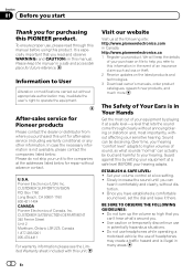
... battery. In the event of any attached speakers may also heat up and cause minor burns. ! If you start Section 01 English Before connecting/ installing the amplifier WARNING ! Always keep the volume low enough to avoid the risk of electric shock or short circuit during installation. About the Protection function The Protection function will shut down. ! If the speaker output terminal and speaker wire is cut off and check the power...
... battery. In the event of any attached speakers may also heat up and cause minor burns. ! If you start Section 01 English Before connecting/ installing the amplifier WARNING ! Always keep the volume low enough to avoid the risk of electric shock or short circuit during installation. About the Protection function The Protection function will shut down. ! If the speaker output terminal and speaker wire is cut off and check the power...
Owner's Manual
Page 4
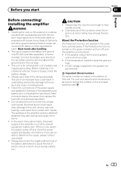
... preout maximum output level of the head unit, so that of 4 V or more, adjust level to match that volume can remain unchanged and to indicate power ON. Setting gain properly ! For use a flathead screwdriver if needed. 1 LPF (low-pass filter) switch Switch the settings based on the connected speaker. ! In such cases, please contact the nearest authorized Pioneer Service Station. If distortion occurs when the car stereo volume is turned up, turn these controls to lower level. When outputting high volume sound etc...
... preout maximum output level of the head unit, so that of 4 V or more, adjust level to match that volume can remain unchanged and to indicate power ON. Setting gain properly ! For use a flathead screwdriver if needed. 1 LPF (low-pass filter) switch Switch the settings based on the connected speaker. ! In such cases, please contact the nearest authorized Pioneer Service Station. If distortion occurs when the car stereo volume is turned up, turn these controls to lower level. When outputting high volume sound etc...
Owner's Manual
Page 5
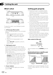
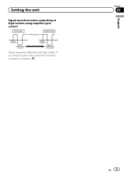
English Section 02 En 5 Setting the unit Signal waveform when outputting at high volume using amplifier gain control Signal waveform distorted with high output, if you raise the gain of the amplifier the power changes only slightly.
English Section 02 En 5 Setting the unit Signal waveform when outputting at high volume using amplifier gain control Signal waveform distorted with high output, if you raise the gain of the amplifier the power changes only slightly.
Owner's Manual
Page 6
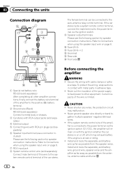
... remote control wire of the power supply to feed power to the power terminal via the ignition switch. 9 Speaker output terminals Please see the following section for speaker connection instructions. To protect the wiring, wrap sections in - Never cut the insulation of the amplifier is connected to other amplifier connections, finally connect the battery wire terminal of the amplifier to the positive (+) battery terminal. 2 Ground wire (Black) RD-223 (sold battery wire, ground wire, speaker wires and the amplifier as far away as possible from the antenna, antenna cable...
... remote control wire of the power supply to feed power to the power terminal via the ignition switch. 9 Speaker output terminals Please see the following section for speaker connection instructions. To protect the wiring, wrap sections in - Never cut the insulation of the amplifier is connected to other amplifier connections, finally connect the battery wire terminal of the amplifier to the positive (+) battery terminal. 2 Ground wire (Black) RD-223 (sold battery wire, ground wire, speaker wires and the amplifier as far away as possible from the antenna, antenna cable...
Owner's Manual
Page 7
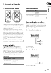
... subwoofer Speaker channel Two-channel output One-channel output Power MAX input: Min. 120 W MAX input: Min. 370 W English Section 03 Speaker impedance is a risk of fire, smoke or damage. For bridged mode for a two-channel amplifier, with a 4 W load, either wire two 8 W speakers in parallel for a 4 W load or a single 4 W speaker per channel. Speaker impedance is 2 W to 8 W for bridging shown on rear: two 8 W speakers in parallel, Left + and Right * (Diagram A) or use a single 4 W speaker. About suitable specification of speaker Ensure speakers...
... subwoofer Speaker channel Two-channel output One-channel output Power MAX input: Min. 120 W MAX input: Min. 370 W English Section 03 Speaker impedance is a risk of fire, smoke or damage. For bridged mode for a two-channel amplifier, with a 4 W load, either wire two 8 W speakers in parallel for a 4 W load or a single 4 W speaker per channel. Speaker impedance is 2 W to 8 W for bridging shown on rear: two 8 W speakers in parallel, Left + and Right * (Diagram A) or use a single 4 W speaker. About suitable specification of speaker Ensure speakers...
Owner's Manual
Page 8
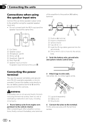
... 4 Fuse (30 A) × 2 5 Insert the O-ring rubber grommet into the vehicle body. 6 Drill a 14 mm (1/2 in.) hole into the vehicle body. 2 Twist the battery wire, ground wire and system remote control wire. Twist Connecting the power terminal The use of a special red battery and ground wire RD-223, available separately, is not securely fixed to the terminal using the supplied speaker input wire. ! Section 03 Connecting the units Connections when using the speaker input wire Connect the car stereo speaker output wires to the amplifier using the terminal screws...
... 4 Fuse (30 A) × 2 5 Insert the O-ring rubber grommet into the vehicle body. 6 Drill a 14 mm (1/2 in.) hole into the vehicle body. 2 Twist the battery wire, ground wire and system remote control wire. Twist Connecting the power terminal The use of a special red battery and ground wire RD-223, available separately, is not securely fixed to the terminal using the supplied speaker input wire. ! Section 03 Connecting the units Connections when using the speaker input wire Connect the car stereo speaker output wires to the amplifier using the terminal screws...
Owner's Manual
Page 9
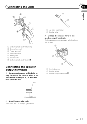
... 1 Lug (sold separately) 2 Speaker wire 3 Connect the speaker wires to wire ends. Fix the speaker wires securely with the terminal screws. 1 Terminal screws 2 Speaker wires 3 Speaker output terminals 2 Attach lugs to the speaker output terminals. Connecting the units Section 03 English 1 System remote control terminal 2 Ground terminal 3 Power terminal 4 Terminal screws 5 Battery wire 6 Ground wire 7 System remote control wire Connecting the speaker output terminals 1 Use wire cutters or a utility knife to strip the end of wire and then twist the wire. Use pliers, etc., to crimp...
... 1 Lug (sold separately) 2 Speaker wire 3 Connect the speaker wires to wire ends. Fix the speaker wires securely with the terminal screws. 1 Terminal screws 2 Speaker wires 3 Speaker output terminals 2 Attach lugs to the speaker output terminals. Connecting the units Section 03 English 1 System remote control terminal 2 Ground terminal 3 Power terminal 4 Terminal screws 5 Battery wire 6 Ground wire 7 System remote control wire Connecting the speaker output terminals 1 Use wire cutters or a utility knife to strip the end of wire and then twist the wire. Use pliers, etc., to crimp...
Owner's Manual
Page 10
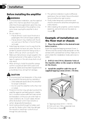
... fuel/brake lines, wiring) from being cut by vibration of the amplifier, or become loose causing the amplifier to install the amplifier, always confirm no parts are used, they make temporary connections and check to prevent wires from damage. To ensure proper heat dissipation of installation on the chassis. 3 Install the amplifier with the dri- To ensure proper installation, use under high-volume conditions, etc. Install tapping screws in such a way that...
... fuel/brake lines, wiring) from being cut by vibration of the amplifier, or become loose causing the amplifier to install the amplifier, always confirm no parts are used, they make temporary connections and check to prevent wires from damage. To ensure proper heat dissipation of installation on the chassis. 3 Install the amplifier with the dri- To ensure proper installation, use under high-volume conditions, etc. Install tapping screws in such a way that...
Owner's Manual
Page 11
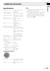
... input level / impedance: RCA 6.5 V / 22 kW Speaker 26 V / 22 kW CEA2006 Specifications Notes ! Power output 60 W RMS × 2 Channels (at 14.4 V, 2 W, 1 kHz, ≦ 1.0 % THD+N) Load impedance 4 W (2 W to 8 W allowable) Frequency response 10 Hz to 70 kHz (+0 dB, - 3 dB) Signal-to-noise ratio 98 dB (IHF-A network) Distortion 0.05 % (10 W, 1 kHz) Low pass filter: Cut off frequency 80 Hz Cut off slope 12 dB/oct Gain control: RCA...
... input level / impedance: RCA 6.5 V / 22 kW Speaker 26 V / 22 kW CEA2006 Specifications Notes ! Power output 60 W RMS × 2 Channels (at 14.4 V, 2 W, 1 kHz, ≦ 1.0 % THD+N) Load impedance 4 W (2 W to 8 W allowable) Frequency response 10 Hz to 70 kHz (+0 dB, - 3 dB) Signal-to-noise ratio 98 dB (IHF-A network) Distortion 0.05 % (10 W, 1 kHz) Low pass filter: Cut off frequency 80 Hz Cut off slope 12 dB/oct Gain control: RCA...

Owner's Manual
Page 36
..., Belgium/Belgique TEL: (0) 3/570.05.11 PIONEER ELECTRONICS ASIACENTRE PTE. Tous droits de reproduction et de traduction réservés. PIONEER CORPORATION 1-1, Shin-ogura, Saiwai-ku, Kawasaki-shi, Kanagawa 212-0031, JAPAN PIONEER ELECTRONICS (USA) INC. Blvd.Manuel Avila Camacho ...;901-6 0852) 2848-6488 ã 2011 PIONEER CORPORATION. de C.V. P.O. Box 1540, Long Beach, California 90801-1540, U.S.A. LTD. 5 Arco Lane, Heatherton, Victoria, 3202 Australia TEL: (03) 9586-6300 PIONEER ELECTRONICS OF CANADA, INC. 340 Ferrier Street, Unit 2, Markham, Ontario L3R 2Z5, Canada TEL...
..., Belgium/Belgique TEL: (0) 3/570.05.11 PIONEER ELECTRONICS ASIACENTRE PTE. Tous droits de reproduction et de traduction réservés. PIONEER CORPORATION 1-1, Shin-ogura, Saiwai-ku, Kawasaki-shi, Kanagawa 212-0031, JAPAN PIONEER ELECTRONICS (USA) INC. Blvd.Manuel Avila Camacho ...;901-6 0852) 2848-6488 ã 2011 PIONEER CORPORATION. de C.V. P.O. Box 1540, Long Beach, California 90801-1540, U.S.A. LTD. 5 Arco Lane, Heatherton, Victoria, 3202 Australia TEL: (03) 9586-6300 PIONEER ELECTRONICS OF CANADA, INC. 340 Ferrier Street, Unit 2, Markham, Ontario L3R 2Z5, Canada TEL...


