Service Manual
Page 1
...8654, Japan PIONEER ELECTRONICS SERVICE, INC. IZE SEPT. 1998 Printed in Japan P.O. SAFETY INFORMATION 2 2. • DV-515 STANDBY POWER OFF ON VIRTUAL DOLBY SURROND 10 KEY OPERATION TITLE +10 1 2 3 4 5 6 7 8 9 0 0 FL OFF 4 1 ¡ ¢ 7 £¥8 DVD PLAYER DV-515 DV-414 ORDER NO.... AC120V 1 • Refer to the service guide RRV2004 for DV-515. CONTENTS 1. AC110-127/220-240V 3 RAM - AC120V 1 KC - Box 1760, Long Beach, CA 90801-1760...
...8654, Japan PIONEER ELECTRONICS SERVICE, INC. IZE SEPT. 1998 Printed in Japan P.O. SAFETY INFORMATION 2 2. • DV-515 STANDBY POWER OFF ON VIRTUAL DOLBY SURROND 10 KEY OPERATION TITLE +10 1 2 3 4 5 6 7 8 9 0 0 FL OFF 4 1 ¡ ¢ 7 £¥8 DVD PLAYER DV-515 DV-414 ORDER NO.... AC120V 1 • Refer to the service guide RRV2004 for DV-515. CONTENTS 1. AC110-127/220-240V 3 RAM - AC120V 1 KC - Box 1760, Long Beach, CA 90801-1760...
Service Manual
Page 3
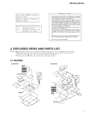
...disassembly. 2.1 PACKING • For DV-515 7 5 6 1 (DV-515/RAM only) 15 4 16 3 10 8 10 14 17 18 FRONT 13 • For DV-414 4 3 8 10 11 14 10 12 1 6 5 7 13 DV-414 /KC only 19 15 16 19 DV-414 /KC only 3 DV-515, DV-414 IMPORTANT THIS PIONNER APPARATUS CONTAINS LASER... OF CLASS 1. LASER DIODE CHARACTERISTICS FOR DVD : MAXIMUM OUTPUT POWER : 7 mw WAVELENGTH : 650 ...
...disassembly. 2.1 PACKING • For DV-515 7 5 6 1 (DV-515/RAM only) 15 4 16 3 10 8 10 14 17 18 FRONT 13 • For DV-414 4 3 8 10 11 14 10 12 1 6 5 7 13 DV-414 /KC only 19 15 16 19 DV-414 /KC only 3 DV-515, DV-414 IMPORTANT THIS PIONNER APPARATUS CONTAINS LASER... OF CLASS 1. LASER DIODE CHARACTERISTICS FOR DVD : MAXIMUM OUTPUT POWER : 7 mw WAVELENGTH : 650 ...

Service Manual
Page 5
... only 17 12 13 14 DV-515, DV-414 16 11 DV-515/RL only 5 10 4 9 6 7 8 3 2 10 Refer to "2.3 FRONT PANEL SECTION" (1) EXTERIOR SECTION PARTS LIST Mark No. 1 2 3 4 5 Description Bonnet Case S Tray Panel DVD Plate POWER Button PW Button Joint Part No. Symbol and Description 1 Bonnet Case S 2 Tray Panel 4 POWER Button 5 PW Button Joint 6 Tray...
... only 17 12 13 14 DV-515, DV-414 16 11 DV-515/RL only 5 10 4 9 6 7 8 3 2 10 Refer to "2.3 FRONT PANEL SECTION" (1) EXTERIOR SECTION PARTS LIST Mark No. 1 2 3 4 5 Description Bonnet Case S Tray Panel DVD Plate POWER Button PW Button Joint Part No. Symbol and Description 1 Bonnet Case S 2 Tray Panel 4 POWER Button 5 PW Button Joint 6 Tray...

Service Manual
Page 41
... CONNECTOR 6P PDTA124EK SLP4118C51H SLP9118C51H RSG1030 CKSQYF104Z25 RS1/10S J 06R-FJ G DILB ASSY SEMICONDUCTOR D301 OTHERS CN301 FJ CONNECTOR 4P PL301 LAMP (DVD ILUM.) MA111 04R-FJ VEL1022 DV-515, DV-414 Mark No. Description H DVDM ASSY SEMICONDUCTORS IC301 IC371 IC401 IC352 IC251 Part No. Description CAPACITORS C101-C103,C105,C117 C108,C110-C113...
... CONNECTOR 6P PDTA124EK SLP4118C51H SLP9118C51H RSG1030 CKSQYF104Z25 RS1/10S J 06R-FJ G DILB ASSY SEMICONDUCTOR D301 OTHERS CN301 FJ CONNECTOR 4P PL301 LAMP (DVD ILUM.) MA111 04R-FJ VEL1022 DV-515, DV-414 Mark No. Description H DVDM ASSY SEMICONDUCTORS IC301 IC371 IC401 IC352 IC251 Part No. Description CAPACITORS C101-C103,C105,C117 C108,C110-C113...
Service Manual
Page 45
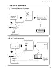
H: 10msec/div. DC mode TV trigger 45 6.4 ELECTRICAL ADJUSTMENT 1 16MHz Master Clock Adjustment DV-515, DV-414 • Normal mode • Power ON DVDM ASSY VC901 16.934400MHz ± 80Hz START DVDM ASSY Player IC904 5 2 VCO Offset Adjustment Frequency counter • Normal mode • Play the DVD test disc DVDM ASSY VC301 START DVDM ASSY IC302 1 Player Probe (10:1) 1.9V± 0.1V GND CH1 CH2 (X) (Y) Oscilloscope V: 50mV/div.
H: 10msec/div. DC mode TV trigger 45 6.4 ELECTRICAL ADJUSTMENT 1 16MHz Master Clock Adjustment DV-515, DV-414 • Normal mode • Power ON DVDM ASSY VC901 16.934400MHz ± 80Hz START DVDM ASSY Player IC904 5 2 VCO Offset Adjustment Frequency counter • Normal mode • Play the DVD test disc DVDM ASSY VC301 START DVDM ASSY IC302 1 Player Probe (10:1) 1.9V± 0.1V GND CH1 CH2 (X) (Y) Oscilloscope V: 50mV/div.

Service Manual
Page 46
...(NC) (NC) − Power supply pin O Non connection O Non connection 11 P25 (NC) O Non connection 12 P24 LAMP O DVD lamp ON/OFF H: ON 13 P23 XREADY 14 P22 15 P21 16 P20 SCK SO SI Communication handshake line with O system controller L: Communication...system controller I Communication data input with I system controller H: Communication permission I Not used 40 P33 P33 I Remote control signal input −- DV-515, DV-414 7. GENERAL INFORMATION 7.1 PARTS 7.1.1 IC • The information shown in the schematic diagrams. • List of IC PE5018B, PE5012A, PD3381A ...
...(NC) (NC) − Power supply pin O Non connection O Non connection 11 P25 (NC) O Non connection 12 P24 LAMP O DVD lamp ON/OFF H: ON 13 P23 XREADY 14 P22 15 P21 16 P20 SCK SO SI Communication handshake line with O system controller L: Communication...system controller I Communication data input with I system controller H: Communication permission I Not used 40 P33 P33 I Remote control signal input −- DV-515, DV-414 7. GENERAL INFORMATION 7.1 PARTS 7.1.1 IC • The information shown in the schematic diagrams. • List of IC PE5018B, PE5012A, PD3381A ...

Service Manual
Page 47
...O Not used I /O Function O DSP parallel command setting output "L" O Address strobe of error rate Measureable by using timer 1 and 2. DV-515, DV-414 PE5012A (DVDM ASSY : IC501) • Mechanism Control IC • Pin Function No. Pin Name 33 XCSB 34 ASTB 35 XRESET 36... converter I Reference voltage input for A/D converter O 650nm laser diode ON signal O 780nm laser diode ON signal O "H": AGC of RFIC turns to OFF O H: DVD, L: CD O Tracking error switch (H: 1 beam, L: 3 beams) I/O Tracking balance adjustment A O Not used I DSP command reception is possible "L" I System...
...O Not used I /O Function O DSP parallel command setting output "L" O Address strobe of error rate Measureable by using timer 1 and 2. DV-515, DV-414 PE5012A (DVDM ASSY : IC501) • Mechanism Control IC • Pin Function No. Pin Name 33 XCSB 34 ASTB 35 XRESET 36... converter I Reference voltage input for A/D converter O 650nm laser diode ON signal O 780nm laser diode ON signal O "H": AGC of RFIC turns to OFF O H: DVD, L: CD O Tracking error switch (H: 1 beam, L: 3 beams) I/O Tracking balance adjustment A O Not used I DSP command reception is possible "L" I System...
Service Manual
Page 53
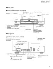
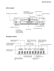
STANDBY indicator (STANDBY) Disc illumination Open/Close 0 button Turned off the display window and this button turn off when a disc other than a DVD is used . Digital Output Jacks (Coaxial, Optical) This is played back. S-Video output jack* Video output jack* Control input jack Component video output jacks**... model) Number buttons Display window VIRTUAL DOLBY SURROUND button 7 Rear panel Forward ¡ ¢ button Reverse 4 1 button FL OFF button Pressing this indicator ON. DV-515, DV-414 7 Front panel ¶ Illustration shows the Round blade 2-pin AC plug model.
STANDBY indicator (STANDBY) Disc illumination Open/Close 0 button Turned off the display window and this button turn off when a disc other than a DVD is used . Digital Output Jacks (Coaxial, Optical) This is played back. S-Video output jack* Video output jack* Control input jack Component video output jacks**... model) Number buttons Display window VIRTUAL DOLBY SURROUND button 7 Rear panel Forward ¡ ¢ button Reverse 4 1 button FL OFF button Pressing this indicator ON. DV-515, DV-414 7 Front panel ¶ Illustration shows the Round blade 2-pin AC plug model.
Service Manual
Page 55
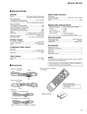
...audio output 200 mVrms (1 kHz, -20 dB) Number of channels 2 Jacks RCA Digital audio characteristics Frequency response 4 Hz to 44 kHz (DVD fs: 96 kHz) S/N ratio 115 dB Dynamic range 103 dB Total harmonic distortion 0.002 % Wow and flutter Limit of Dolby Laboratories Licensing... is supplied.) Other included items : • Operating instructions (this product are trademarks of measurement (±0.001% W. DV-515, DV-414 SPECIFICATIONS General System DVD system,Video CD system and Compact Disc digital audio system Power requirements Flat blade 2-pin AC plug model AC 110 V,...
...audio output 200 mVrms (1 kHz, -20 dB) Number of channels 2 Jacks RCA Digital audio characteristics Frequency response 4 Hz to 44 kHz (DVD fs: 96 kHz) S/N ratio 115 dB Dynamic range 103 dB Total harmonic distortion 0.002 % Wow and flutter Limit of Dolby Laboratories Licensing... is supplied.) Other included items : • Operating instructions (this product are trademarks of measurement (±0.001% W. DV-515, DV-414 SPECIFICATIONS General System DVD system,Video CD system and Compact Disc digital audio system Power requirements Flat blade 2-pin AC plug model AC 110 V,...
Service Manual
Page 57
Open/Close 0 button Play/Pause 6 button Stop 7 button Remote sensor STANDBY STANDBY/ON DVD PLAYER ÛN¿¯,¯ FL OFF Component Video Output 96 kHz ANGLE GUI TITLE CHP/TRK LAST MEMORY DOLBY REMAIN TOTAL DIGITAL 0 41 ¡ &#... with a sampling frequency of side Indicates remaining playback time 57 Indicates location for Last Memory is in memory. Indicates that a chapter/ track is played back. DV-515, DV-414 7 Front panel STANDBY indicator (STANDBY) Disc illumination Turned off when a disc other than...
Open/Close 0 button Play/Pause 6 button Stop 7 button Remote sensor STANDBY STANDBY/ON DVD PLAYER ÛN¿¯,¯ FL OFF Component Video Output 96 kHz ANGLE GUI TITLE CHP/TRK LAST MEMORY DOLBY REMAIN TOTAL DIGITAL 0 41 ¡ &#... with a sampling frequency of side Indicates remaining playback time 57 Indicates location for Last Memory is in memory. Indicates that a chapter/ track is played back. DV-515, DV-414 7 Front panel STANDBY indicator (STANDBY) Disc illumination Turned off when a disc other than...

Service Manual
Page 58
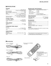
... AUDIO OUT R L AC IN Video output select switch * : For Video and S Video output. ** : For component video output. Type Disc Format Video CD NTSC PAL DVD NTSC PAL CD, No disc Stop mode Output format Position of the screen. NTSC = PAL, PAL = NTSC conversion is possible on...format will be selected. On some TVs, the picture may roll. PAL NTSC NTSC PAL PAL PAL NTSC or PAL NTSC PAL NTSC or PAL 1. DV-515, DV-414 7 Rear panel Digital Output Jacks (Coaxial, Optical) This is used for U.S. Set digital output to view NTSC disc because the picture may shrink ...
... AUDIO OUT R L AC IN Video output select switch * : For Video and S Video output. ** : For component video output. Type Disc Format Video CD NTSC PAL DVD NTSC PAL CD, No disc Stop mode Output format Position of the screen. NTSC = PAL, PAL = NTSC conversion is possible on...format will be selected. On some TVs, the picture may roll. PAL NTSC NTSC PAL PAL PAL NTSC or PAL NTSC PAL NTSC or PAL 1. DV-515, DV-414 7 Rear panel Digital Output Jacks (Coaxial, Optical) This is used for U.S. Set digital output to view NTSC disc because the picture may shrink ...
Service Manual
Page 59
... 200 mVrms (1 kHz, -20 dB) Number of channels 2 Jacks RCA Digital audio characteristics Frequency response 4 Hz to 44 kHz (DVD fs: 96 kHz) S/N ratio 115 dB Dynamic range 102 dB Total harmonic distortion 0.002 % Wow and flutter Limit of Dolby Laboratories... models only 1 NOTE: The specifications and design of this manual) 59 Output level 1 Vp-p (75 Ω ) C (color) - DV-515, DV-414 SPECIFICATIONS General System DVD system and Compact Disc digital audio system Power requirements AC 120 V, 60 Hz Power consumption 15 W Power consumption in standby mode 1.5 W Weight ...
... 200 mVrms (1 kHz, -20 dB) Number of channels 2 Jacks RCA Digital audio characteristics Frequency response 4 Hz to 44 kHz (DVD fs: 96 kHz) S/N ratio 115 dB Dynamic range 102 dB Total harmonic distortion 0.002 % Wow and flutter Limit of Dolby Laboratories... models only 1 NOTE: The specifications and design of this manual) 59 Output level 1 Vp-p (75 Ω ) C (color) - DV-515, DV-414 SPECIFICATIONS General System DVD system and Compact Disc digital audio system Power requirements AC 120 V, 60 Hz Power consumption 15 W Power consumption in standby mode 1.5 W Weight ...


