Owner's Manual
Page 4
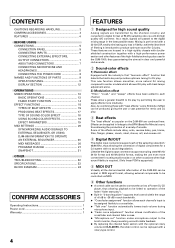
...play . CONTENTS CAUTIONS REGARDING HANDLING 3 CONFIRM ACCESSORIES 4 FEATURES 4 BEFORE USING CONNECTIONS 5 CONNECTION PANEL 5 CONNECTING INPUTS 6 CONNECTING EXTERNAL EFFECTORS, OUTPUT CONNECTORS 7 ABOUT MIDI CONNECTORS 7 CONNECTING MICROPHONE AND HEADPHONES...reverse roll. 4 Digital IN/OUT The digital input connectors support each channel. Some of the DJM-800 can be output in MIDI signal format, allowing external components to apply...features of the high-fidelity technology also used to connect the unit to a Pioneer DJ CD player, thus allowing playback to be linked to operation of the...
...play . CONTENTS CAUTIONS REGARDING HANDLING 3 CONFIRM ACCESSORIES 4 FEATURES 4 BEFORE USING CONNECTIONS 5 CONNECTION PANEL 5 CONNECTING INPUTS 6 CONNECTING EXTERNAL EFFECTORS, OUTPUT CONNECTORS 7 ABOUT MIDI CONNECTORS 7 CONNECTING MICROPHONE AND HEADPHONES...reverse roll. 4 Digital IN/OUT The digital input connectors support each channel. Some of the DJM-800 can be output in MIDI signal format, allowing external components to apply...features of the high-fidelity technology also used to connect the unit to a Pioneer DJ CD player, thus allowing playback to be linked to operation of the...
Owner's Manual
Page 5
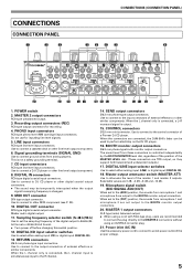
...OUT connector RCA type digital coaxial output connector. When the L channel only is connected, a L+R monaural signal is controlled independently by ...When using a cord with RCA-type plug, users are connected, the DJM-800's fader can be temporarily interrupted when the output signal's sampling frequency is ... be used to an AC power outlet of a Pioneer DJ CD player. Power inlet (AC IN) Use...analog players. RETURN connectors Ø6.3 mm phone-type input connectors. CONNECTIONS CONNECTION PANEL 1 2 3 CONNECTIONS (CONNECTION PANEL) 4 5 6 7 8 AC IN POWER OFF ON MASTER 2 REC ...
...OUT connector RCA type digital coaxial output connector. When the L channel only is connected, a L+R monaural signal is controlled independently by ...When using a cord with RCA-type plug, users are connected, the DJM-800's fader can be temporarily interrupted when the output signal's sampling frequency is ... be used to an AC power outlet of a Pioneer DJ CD player. Power inlet (AC IN) Use...analog players. RETURN connectors Ø6.3 mm phone-type input connectors. CONNECTIONS CONNECTION PANEL 1 2 3 CONNECTIONS (CONNECTION PANEL) 4 5 6 7 8 AC IN POWER OFF ON MASTER 2 REC ...
Owner's Manual
Page 7
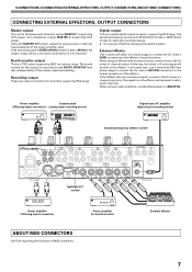
... Power amplifier (for recording, supporting RCA plugs. If the operating panel's STEREO/MONO switch is set to the effector. Booth monitor output This is controlled by the BOOTH MONITOR level dial, independently of L+R channels. Recording output These are output connectors for booth monitor) External effector... When using an effector with Ø6.3 mm phone plugs to connect the DJ mixer's SEND connectors to the DJ mixer's L channel input only. Power amplifier Cassette deck (RCA plug input connectors) (analog input recording device) Digital input AV amplifier (digital input ...
... Power amplifier (for recording, supporting RCA plugs. If the operating panel's STEREO/MONO switch is set to the effector. Booth monitor output This is controlled by the BOOTH MONITOR level dial, independently of L+R channels. Recording output These are output connectors for booth monitor) External effector... When using an effector with Ø6.3 mm phone plugs to connect the DJ mixer's SEND connectors to the DJ mixer's L channel input only. Power amplifier Cassette deck (RCA plug input connectors) (analog input recording device) Digital input AV amplifier (digital input ...
Owner's Manual
Page 9
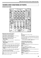
... control dial (MIC 2 LEVEL) Use to adjust the volume of microphones 1 and 2. (adjustable range -12 dB to 0 dB) 5. LINE/DIGITAL (channel 3 to 4): Use to select CD input connectors (line level analog input) or DIGITAL input connectors. Microphone 1 level control dial (MIC 1 LEVEL) Use... analog input) or DIGITAL input connectors. flashes when TALK OVER is output normally. NAMES AND FUNCTIONS OF PARTS (OPERATION PANEL) NAMES AND FUNCTIONS OF PARTS OPERATION PANEL POWER MIC MIC 1 MIC 2 CD /DIGITAL LINE CD /DIGITAL LINE PHONO /DIGITAL LINE PHONO /DIGITAL PHONO MASTER LEVEL...
... control dial (MIC 2 LEVEL) Use to adjust the volume of microphones 1 and 2. (adjustable range -12 dB to 0 dB) 5. LINE/DIGITAL (channel 3 to 4): Use to select CD input connectors (line level analog input) or DIGITAL input connectors. Microphone 1 level control dial (MIC 1 LEVEL) Use... analog input) or DIGITAL input connectors. flashes when TALK OVER is output normally. NAMES AND FUNCTIONS OF PARTS (OPERATION PANEL) NAMES AND FUNCTIONS OF PARTS OPERATION PANEL POWER MIC MIC 1 MIC 2 CD /DIGITAL LINE CD /DIGITAL LINE PHONO /DIGITAL LINE PHONO /DIGITAL PHONO MASTER LEVEL...
Owner's Manual
Page 10
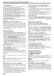
...channel...channels... the channel fader's...channel, and the master audio is output to the R channel...channel, with the CROSS FADER ASSIGN switch; Channel equalizer mid-range adjust dial (MID) Use to adjust the mid-range frequency sound for each channel...channel...channels...channel fader curve response. A: The selected channel is applied equally to channels 1 to 4. ¶ At the left side of the effect monitor and the channel...channel fader approaches its distant position. ...channel fader's output is sent as is to adjust the L/R channel balance for each channel...Channel...channels are mixed. Channel...
...channel...channels... the channel fader's...channel, and the master audio is output to the R channel...channel, with the CROSS FADER ASSIGN switch; Channel equalizer mid-range adjust dial (MID) Use to adjust the mid-range frequency sound for each channel...channel...channels...channel fader curve response. A: The selected channel is applied equally to channels 1 to 4. ¶ At the left side of the effect monitor and the channel...channel fader approaches its distant position. ...channel fader's output is sent as is to adjust the L/R channel balance for each channel...Channel...channels are mixed. Channel...
Owner's Manual
Page 11
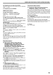
... mode, the mode automatically switches to adjust quantitative parameters for the selected function will flash, and the effect will be applied equally to channels 1 to alternate the MIDI control function between [AUTO] and [TAP]. Effect parameter 2 dial [LEVEL/DEPTH (PARAMETER 2)] Adjusts quantitative ...40. TAP: The display's [TAP] indicator lights, and the BPM is struck. Whenever power is lighted. NAMES AND FUNCTIONS OF PARTS (OPERATION PANEL) 30. Headphones level adjust dial (LEVEL) Adjusts the output level of the effect (P. 18). 43. Effect button/indicator (ON/OFF) Sets ...
... mode, the mode automatically switches to adjust quantitative parameters for the selected function will flash, and the effect will be applied equally to channels 1 to alternate the MIDI control function between [AUTO] and [TAP]. Effect parameter 2 dial [LEVEL/DEPTH (PARAMETER 2)] Adjusts quantitative ...40. TAP: The display's [TAP] indicator lights, and the BPM is struck. Whenever power is lighted. NAMES AND FUNCTIONS OF PARTS (OPERATION PANEL) 30. Headphones level adjust dial (LEVEL) Adjusts the output level of the effect (P. 18). 43. Effect button/indicator (ON/OFF) Sets ...
Owner's Manual
Page 13
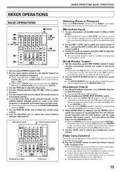
... the [MASTER] is ON). ¶ When set the CROSS FADER ASSIGN switch to either cross fader channel A or channel B, and operate the cross fader lever. ¶ When not using a DIGITAL input, the connection panel's DIGITAL/ CD switch or DIGITAL/LINE switch must be set to [CD] or [LINE]. ¶... choose the connected component. ¶ When using CD input or LINE input, the connection panel's DIGITAL/CD switch or DIGITAL/LINE switch must be used to produce an even, neutral rise throughout the channel fader's movement. ¶ At the middle setting, an intermediate curve is ON) increases; when ...
... the [MASTER] is ON). ¶ When set the CROSS FADER ASSIGN switch to either cross fader channel A or channel B, and operate the cross fader lever. ¶ When not using a DIGITAL input, the connection panel's DIGITAL/ CD switch or DIGITAL/LINE switch must be set to [CD] or [LINE]. ¶... choose the connected component. ¶ When using CD input or LINE input, the connection panel's DIGITAL/CD switch or DIGITAL/LINE switch must be used to produce an even, neutral rise throughout the channel fader's movement. ¶ At the middle setting, an intermediate curve is ON) increases; when ...
Owner's Manual
Page 22
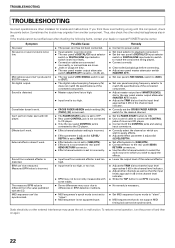
... is set to [MIN]. ÷ Effect selecter is not set to [SND/RTN]. ÷ Effector is not connected to rear panel SEND/RETURN connector. ÷ Effect channel selector is set to incorrectly. ÷ Input level from the value published with some tracks. ÷ Some differences may occur due ...and malfunctions. If the trouble cannot be synchronized. BPM can 't be rectified even after checking the following items, contact your dealer or nearest PIONEER service center. Symptom No power No sound, or sound volume is necessary. ÷ Set MIDI sequencer's sync mode to connect the CONTROL...
... is set to [MIN]. ÷ Effect selecter is not set to [SND/RTN]. ÷ Effector is not connected to rear panel SEND/RETURN connector. ÷ Effect channel selector is set to incorrectly. ÷ Input level from the value published with some tracks. ÷ Some differences may occur due ...and malfunctions. If the trouble cannot be synchronized. BPM can 't be rectified even after checking the following items, contact your dealer or nearest PIONEER service center. Symptom No power No sound, or sound volume is necessary. ÷ Set MIDI sequencer's sync mode to connect the CONTROL...

