Owner's Manual
Page 2
... PIONEER authorized service center or your outlet, consult an electrician for replacement of uninsulated "dangerous voltage" within an equilateral triangle, is the same. IMPORTANT NOTICE - THIS IS FOR YOUR SECURITY. However, there is used, use shielded cables and connectors for connections. D3-4-2-1-6_A_En CAUTION The POWER switch on the power cord, or pinch the cord. Since the power cord serves as radios and televisions, use...
... PIONEER authorized service center or your outlet, consult an electrician for replacement of uninsulated "dangerous voltage" within an equilateral triangle, is the same. IMPORTANT NOTICE - THIS IS FOR YOUR SECURITY. However, there is used, use shielded cables and connectors for connections. D3-4-2-1-6_A_En CAUTION The POWER switch on the power cord, or pinch the cord. Since the power cord serves as radios and televisions, use...
Owner's Manual
Page 4
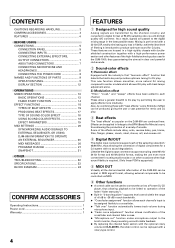
... MICROPHONE AND HEADPHONES 8 CONNECTING THE POWER CORD 8 NAMES AND FUNCTIONS OF PARTS 9 OPERATION PANEL 9 DISPLAY SECTION 12 OPERATIONS MIXER OPERATIONS 13 BASIC OPERATIONS 13 FADER START FUNCTION 14 EFFECT FUNCTIONS 15 TYPES OF BEAT EFFECTS 15 PRODUCING BEAT EFFECTS 17 TYPE OF SOUND-COLOR EFFECT 18 USING SOUND-COLOR EFFECTS 18 EFFECT PARAMETERS 19 MIDI SETTINGS 20 SYNCHRONIZING AUDIO SIGNALS TO EXTERNAL SEQUENCER, OR USING DJM-800 INFORMATION TO OPERATE AN EXTERNAL SEQUENCER 20 MIDI MESSAGES 20 PROGRAM CHANGE 21 SNAPSHOT 21 OTHER TROUBLESHOOTING 22 SPECIFICATIONS 23 BLOCK...
... MICROPHONE AND HEADPHONES 8 CONNECTING THE POWER CORD 8 NAMES AND FUNCTIONS OF PARTS 9 OPERATION PANEL 9 DISPLAY SECTION 12 OPERATIONS MIXER OPERATIONS 13 BASIC OPERATIONS 13 FADER START FUNCTION 14 EFFECT FUNCTIONS 15 TYPES OF BEAT EFFECTS 15 PRODUCING BEAT EFFECTS 17 TYPE OF SOUND-COLOR EFFECT 18 USING SOUND-COLOR EFFECTS 18 EFFECT PARAMETERS 19 MIDI SETTINGS 20 SYNCHRONIZING AUDIO SIGNALS TO EXTERNAL SEQUENCER, OR USING DJM-800 INFORMATION TO OPERATE AN EXTERNAL SEQUENCER 20 MIDI MESSAGES 20 PROGRAM CHANGE 21 SNAPSHOT 21 OTHER TROUBLESHOOTING 22 SPECIFICATIONS 23 BLOCK...
Owner's Manual
Page 5
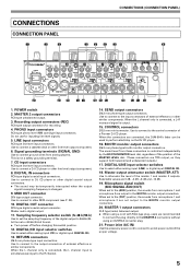
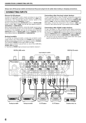
... R channel. 14. Use to connect to select either analog input (LINE) or digital input (DIGITAL IN). 18. DIGITAL/CD input selector switches Use to other line level output component. 6. Microphone signal switch (MIC SIGNAL ADD/CUT) When set to the [CUT] position, the sounds from these connectors is changed. 9. Use to connect to the BOOTH monitor output connectors. MASTER 1 output connectors XLR type (male) balanced output. ÷ When using a cord with RCA-type plug, users are connected, the DJM-800's fader can be temporarily interrupted when the output signal's sampling...
... R channel. 14. Use to connect to select either analog input (LINE) or digital input (DIGITAL IN). 18. DIGITAL/CD input selector switches Use to other line level output component. 6. Microphone signal switch (MIC SIGNAL ADD/CUT) When set to the [CUT] position, the sounds from these connectors is changed. 9. Use to connect to the BOOTH monitor output connectors. MASTER 1 output connectors XLR type (male) balanced output. ÷ When using a cord with RCA-type plug, users are connected, the DJM-800's fader can be temporarily interrupted when the output signal's sampling...
Owner's Manual
Page 6
... provided for channel 1. DIGITAL/LINE switch Input selector switch DIGITAL/CD switch AC IN POWER OFF ON MASTER 2 REC L 1GND R 2HOT 3COLD SIGNAL GND PHONO LINE L PHONO LINE L SIGNAL GND PHONO CD L LINE CD L CONTROL CONTROL CONTROL CONTROL R R DIGITAL LINE MASTER ATT -3dB0dB -6dB -12dB DIGITAL LINE R DIGITAL CD R DIGITAL CD DIGITAL IN DIGITAL OUT fs (Hz) 48 k 96 k MIDI OUT R MASTER 1 L ADD CUT MIC SIGNAL R BOOTH (TRS) L R SEND L(MONO) R RETURN L(MONO) LR LR RL LR LR LR CD player, etc. Connecting other digital output devices To use a cassette deck...
... provided for channel 1. DIGITAL/LINE switch Input selector switch DIGITAL/CD switch AC IN POWER OFF ON MASTER 2 REC L 1GND R 2HOT 3COLD SIGNAL GND PHONO LINE L PHONO LINE L SIGNAL GND PHONO CD L LINE CD L CONTROL CONTROL CONTROL CONTROL R R DIGITAL LINE MASTER ATT -3dB0dB -6dB -12dB DIGITAL LINE R DIGITAL CD R DIGITAL CD DIGITAL IN DIGITAL OUT fs (Hz) 48 k 96 k MIDI OUT R MASTER 1 L ADD CUT MIC SIGNAL R BOOTH (TRS) L R SEND L(MONO) R RETURN L(MONO) LR LR RL LR LR LR CD player, etc. Connecting other digital output devices To use a cassette deck...
Owner's Manual
Page 7
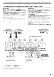
...247; Turn power off before changing this output is controlled by the BOOTH MONITOR level dial, independently of the master output level setting. External effector Use a cable with balanced output MASTER 1 (supporting XLR plugs), and unbalanced output MASTER 2 (supporting RCA plugs). Power amplifier (for recording, supporting RCA plugs. When using an effector with Ø6.3 mm phone plugs to connect the DJ mixer's RETURN connectors to the DJ mixer's L channel input only. Digital output This is a TRS output supporting Ø6.3 mm phone plugs. The sound volume for this switch...
...247; Turn power off before changing this output is controlled by the BOOTH MONITOR level dial, independently of the master output level setting. External effector Use a cable with balanced output MASTER 1 (supporting XLR plugs), and unbalanced output MASTER 2 (supporting RCA plugs). Power amplifier (for recording, supporting RCA plugs. When using an effector with Ø6.3 mm phone plugs to connect the DJ mixer's RETURN connectors to the DJ mixer's L channel input only. Digital output This is a TRS output supporting Ø6.3 mm phone plugs. The sound volume for this switch...
Owner's Manual
Page 8
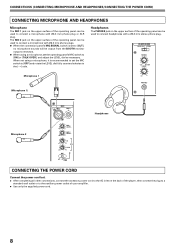
... jack on the upper surface of the operating panel can be used to connect a microphone with Ø6.3 mm phone plugs. ¶ When the connection panel's MIC SIGNAL switch is recommended to set the operating panel's MIC switch to the AC inlet on the upper surface of your amplifier. ÷ Use only the supplied power cord. 8 HEADPHONES MONO SPLIT STEREO MIXING CUE MASTER LEVEL Microphone 1 (Microphone 1) 0 PHONES MIC MIC 1 MIC 2 Headphones Microphone 2 MIC 1 LEVEL 0 MIC 2 LEVEL 0 HI -12 +6 EQ LOW -12 +6 MIC OFF ON TALK OVER CONNECTING THE POWER CORD Connect the power...
... jack on the upper surface of the operating panel can be used to connect a microphone with Ø6.3 mm phone plugs. ¶ When the connection panel's MIC SIGNAL switch is recommended to set the operating panel's MIC switch to the AC inlet on the upper surface of your amplifier. ÷ Use only the supplied power cord. 8 HEADPHONES MONO SPLIT STEREO MIXING CUE MASTER LEVEL Microphone 1 (Microphone 1) 0 PHONES MIC MIC 1 MIC 2 Headphones Microphone 2 MIC 1 LEVEL 0 MIC 2 LEVEL 0 HI -12 +6 EQ LOW -12 +6 MIC OFF ON TALK OVER CONNECTING THE POWER CORD Connect the power...
Owner's Manual
Page 9
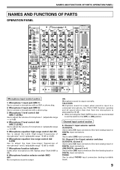
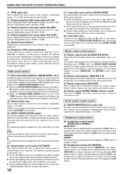
... MONITOR 0 CH FADER CROSS FADER A THRU B A THRU B A THRU B CROSS FADER ASSIGN 22 A B A THRU B 23 44 24 32 BEAT MIDI START AUTO/TAP /STOP 34 TAP 33 35 16 CUE 36 BEAT EFFECTS FLANGER FILTER TRANS PAN PHASER REVERB ROBOT CHORUS REV DLY ECHO ROLL REV ROLL DELAY SND/RTN 26 3 4 MICCF.A 2 CF.B 1 MASTER 27 37 TIME 20 38 LEVEL/DEPTH 21 39 MIN MAX ON/OFF 40 Microphone input control section 1. Microphone 2 level control dial (MIC 2 LEVEL) Use...
... MONITOR 0 CH FADER CROSS FADER A THRU B A THRU B A THRU B CROSS FADER ASSIGN 22 A B A THRU B 23 44 24 32 BEAT MIDI START AUTO/TAP /STOP 34 TAP 33 35 16 CUE 36 BEAT EFFECTS FLANGER FILTER TRANS PAN PHASER REVERB ROBOT CHORUS REV DLY ECHO ROLL REV ROLL DELAY SND/RTN 26 3 4 MICCF.A 2 CF.B 1 MASTER 27 37 TIME 20 38 LEVEL/DEPTH 21 39 MIN MAX ON/OFF 40 Microphone input control section 1. Microphone 2 level control dial (MIC 2 LEVEL) Use...
Owner's Manual
Page 10
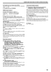
... display the output level from channels set to the [THRU] position, fader start button operation is linked to the operation of the sound from L and R channels. Headphones output switch (MONO SPLIT/STEREO) MONO SPLIT: The audio source selected with the headphones CUE button); TRIM adjust dial Use to adjust the input level for the channel to which a DJ CD player is assigned to [THRU] with the CH FADER curve switch. 19. Fader control section 17. Master output level dial (MASTER LEVEL) Use to adjust the master output level. (adjustable range: -∞ to 0 dB) The master output...
... display the output level from channels set to the [THRU] position, fader start button operation is linked to the operation of the sound from L and R channels. Headphones output switch (MONO SPLIT/STEREO) MONO SPLIT: The audio source selected with the headphones CUE button); TRIM adjust dial Use to adjust the input level for the channel to which a DJ CD player is assigned to [THRU] with the CH FADER curve switch. 19. Fader control section 17. Master output level dial (MASTER LEVEL) Use to adjust the master output level. (adjustable range: -∞ to 0 dB) The master output...
Owner's Manual
Page 11
... turned ON, these indicators light and the color of effect (P. 15). Effect selector (DELAY, ECHO, REV DLY (REVERSE DELAY), PAN, TRANS, FILTER, FLANGER, PHASER, REVERB, ROBOT (ROBOT VOCODER), CHORUS, ROLL, REV ROLL (REVERSE ROLL), SND/RTN (SEND/RETURN)) Use to alternate the MIDI control function between [AUTO] and [TAP]. Effect button/indicator (ON/OFF) Sets selected effect ON/OFF (P. 17). Harmonic Indicators When [HARMONIC] is sent to the TAP mode (manual input). MIDI start and stop button (MIDI START...
... turned ON, these indicators light and the color of effect (P. 15). Effect selector (DELAY, ECHO, REV DLY (REVERSE DELAY), PAN, TRANS, FILTER, FLANGER, PHASER, REVERB, ROBOT (ROBOT VOCODER), CHORUS, ROLL, REV ROLL (REVERSE ROLL), SND/RTN (SEND/RETURN)) Use to alternate the MIDI control function between [AUTO] and [TAP]. Effect button/indicator (ON/OFF) Sets selected effect ON/OFF (P. 17). Harmonic Indicators When [HARMONIC] is sent to the TAP mode (manual input). MIDI start and stop button (MIDI START...
Owner's Manual
Page 12
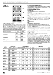
.../1 64/1 ms 1/16 1/8 1/4 1/2 1/1 2/1 4/1 8/1 16/1 ms 1/16 1/8 1/4 1/2 1/1 2/1 4/1 8/1 16/1 Shaded items are displayed for each effect. 4. Switching Operation Upper/ Lower Row Display At MIDI start command has been sent. ¶ Indicator goes out after which the display returns to act as shown below. In manual (TAP) mode, displays the BPM value designated by TAP input, etc. NAMES AND FUNCTIONS OF PARTS (DISPLAY SECTION) DISPLAY SECTION EFFECT SELECT 1 CH SELECT 1234 2 MIC A B MST PARAMETER AUTO TAP MIDI BPM 3 % 4 1.
.../1 64/1 ms 1/16 1/8 1/4 1/2 1/1 2/1 4/1 8/1 16/1 ms 1/16 1/8 1/4 1/2 1/1 2/1 4/1 8/1 16/1 Shaded items are displayed for each effect. 4. Switching Operation Upper/ Lower Row Display At MIDI start command has been sent. ¶ Indicator goes out after which the display returns to act as shown below. In manual (TAP) mode, displays the BPM value designated by TAP input, etc. NAMES AND FUNCTIONS OF PARTS (DISPLAY SECTION) DISPLAY SECTION EFFECT SELECT 1 CH SELECT 1234 2 MIC A B MST PARAMETER AUTO TAP MIDI BPM 3 % 4 1.
Owner's Manual
Page 13
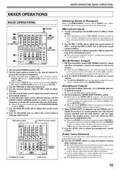
...position, microphone sounds are attenuated by 20 dB. 2. Set the connection panel's MIC SIGNAL switch to select whether microphone sounds are output to the booth monitor. ¶ When set to [DIGITAL]. 3. To use the MIC 2 LEVEL dial to select the source. ¶ The selected CUE button lights brightly. 2. Microphone input Booth monitor output Headphones output STEREO/ MONO Fader curve [Selecting Stereo or Monaural] When the STEREO/MONO switch is output in stereo. 3. Use the CUE buttons (channels 1 to 4, MASTER, effector) to adjust the sound volume of L+R channels. [Microphone Input...
...position, microphone sounds are attenuated by 20 dB. 2. Set the connection panel's MIC SIGNAL switch to select whether microphone sounds are output to the booth monitor. ¶ When set to [DIGITAL]. 3. To use the MIC 2 LEVEL dial to select the source. ¶ The selected CUE button lights brightly. 2. Microphone input Booth monitor output Headphones output STEREO/ MONO Fader curve [Selecting Stereo or Monaural] When the STEREO/MONO switch is output in stereo. 3. Use the CUE buttons (channels 1 to 4, MASTER, effector) to adjust the sound volume of L+R channels. [Microphone Input...
Owner's Manual
Page 14
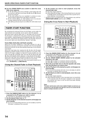
... and reenters standby mode (back cue). * Playback control is possible with the channel fader only with the CROSS FADER ASSIGN switch is set to [THRU]. [Using the Cross Fader to Start Playback] FADER START FUNCTION By connecting the optional Pioneer DJ CD Player control cable, the channel fader and cross fader can be enabled if digital connections are used to start play and back cue play When the CD player assigned to cross fader channel A is set the CD player to "0". 3. Press the FADER START button for the selected channel lights. 2.
... and reenters standby mode (back cue). * Playback control is possible with the channel fader only with the CROSS FADER ASSIGN switch is set to [THRU]. [Using the Cross Fader to Start Playback] FADER START FUNCTION By connecting the optional Pioneer DJ CD Player control cable, the channel fader and cross fader can be enabled if digital connections are used to start play and back cue play When the CD player assigned to cross fader channel A is set the CD player to "0". 3. Press the FADER START button for the selected channel lights. 2.
Owner's Manual
Page 15
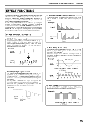
... channels in units of 1/16, 1/8, 1/4, 1/2, 1/1, 2/1, 4/1, 8/1, or 16/1 to right and left very quickly, an effect impossible to the COLOR dials provided for a total of performance effects can produce beat effects linked to the BPM, and sound-color effects linked to perform manually. REVERSE DELAY (One repeat sound) This function allows an inverted delay sound with the music beat. Auto PAN (L-R BALANCE) This function distributes sounds in synch with the rhythm (auto...
... channels in units of 1/16, 1/8, 1/4, 1/2, 1/1, 2/1, 4/1, 8/1, or 16/1 to right and left very quickly, an effect impossible to the COLOR dials provided for a total of performance effects can produce beat effects linked to the BPM, and sound-color effects linked to perform manually. REVERSE DELAY (One repeat sound) This function allows an inverted delay sound with the music beat. Auto PAN (L-R BALANCE) This function distributes sounds in synch with the rhythm (auto...
Owner's Manual
Page 17
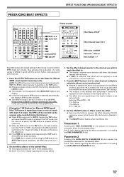
... automatically, the display's BPM counter will flash. ¶ The effective range in the AUTO mode is 70 to 180 BPM. AUTO:The BPM of the input music signal is rotated while holding the TAP button and AUTO/TAP buttons depressed, the BPM can be set in 0.1 units. 2. EFFECT FUNCTIONS (PRODUCING BEAT EFFECTS) PRODUCING BEAT EFFECTS Display example EFFECT SELECT 4 BEAT 2, 3 1 AUTO/TAP TAP 2 3 TIME LEVEL/DEPTH 5 ON/OFF CH SELECT 1234 MIC A B MST PARAMETER AUTO MIDI TAP BPM % Effect Name: DELAY Effect Channel Select: CH 1 BPM value: 120 BPM Parameter 1: 500...
... automatically, the display's BPM counter will flash. ¶ The effective range in the AUTO mode is 70 to 180 BPM. AUTO:The BPM of the input music signal is rotated while holding the TAP button and AUTO/TAP buttons depressed, the BPM can be set in 0.1 units. 2. EFFECT FUNCTIONS (PRODUCING BEAT EFFECTS) PRODUCING BEAT EFFECTS Display example EFFECT SELECT 4 BEAT 2, 3 1 AUTO/TAP TAP 2 3 TIME LEVEL/DEPTH 5 ON/OFF CH SELECT 1234 MIC A B MST PARAMETER AUTO MIDI TAP BPM % Effect Name: DELAY Effect Channel Select: CH 1 BPM value: 120 BPM Parameter 1: 500...
Owner's Manual
Page 19
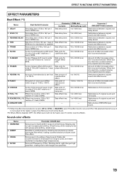
... sounds. Sets cutoff frequency of BPM. When dial is turned fully counterclockwise, only original sound is output. 9 REVERB (*2) Amount of reverberation is set from Sets amount of 1 to 1 cutoff time shift. Sets effect time. 1 to 4 000 (ms) Sets balance of original sound and roll sound. 13 REVERSE ROLL (*2) Effect time is set as 1/16 to effector. Sets volume of RETURN input sound. (*1) When the effect channel selector is set to [CF.A], [CF.B], or [MASTER], even if the effect monitor...
... sounds. Sets cutoff frequency of BPM. When dial is turned fully counterclockwise, only original sound is output. 9 REVERB (*2) Amount of reverberation is set from Sets amount of 1 to 1 cutoff time shift. Sets effect time. 1 to 4 000 (ms) Sets balance of original sound and roll sound. 13 REVERSE ROLL (*2) Effect time is set as 1/16 to effector. Sets volume of RETURN input sound. (*1) When the effect channel selector is set to [CF.A], [CF.B], or [MASTER], even if the effect monitor...
Owner's Manual
Page 20
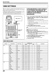
... be set the power switch to 250 BPM. While holding the MIDI START/STOP button depressed, set and stored in memory. 1. MIDI SETTINGS MIDI SETTINGS MIDI is an acronym for "Musical Instrument Digital Interface" and refers to enable the transmission and receipt of data. A MIDI cable is used to OFF. Press the MIDI START/STOP button. ¶ The selected MIDI channel will enter the MIDI setting mode. 2. Set power to output the timing clock. 2. Use a commercially available MIDI cable to connect the DJM-800's MIDI OUT connector to the MIDI sequencer's MIDI...
... be set the power switch to 250 BPM. While holding the MIDI START/STOP button depressed, set and stored in memory. 1. MIDI SETTINGS MIDI SETTINGS MIDI is an acronym for "Musical Instrument Digital Interface" and refers to enable the transmission and receipt of data. A MIDI cable is used to OFF. Press the MIDI START/STOP button. ¶ The selected MIDI channel will enter the MIDI setting mode. 2. Set power to output the timing clock. 2. Use a commercially available MIDI cable to connect the DJM-800's MIDI OUT connector to the MIDI sequencer's MIDI...
Owner's Manual
Page 21
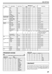
... See "PROGRAM CHANGE" below. minus values are transmitted. MIDI SETTINGS Category CH4 CROSS FADER FADER CURVE MASTER BOOTH EFFECT Switch Name TRIM HI MID LOW COLOR CUE FADER CF ASSIGN CROSS FADER CH CURVE CROSS CURVE MASTER LEVEL BALANCE CUE MONITOR BEAT LEFT BEAT RIGHT AUTO/TAP TAP CUE EFFECT SELECT CH SELECT TIME MIC (SOUND COLOR FX) (FADER START) (HEAD PHONES) MIDI LEVEL/DEPTH EFFECT ON/OFF HI LOW HARMONIC SWEEP CRUSH FILTER 1 2 3 4 MIXING LEVEL START STOP Switch Type VR VR VR VR VR BUTTON VR SW...
... See "PROGRAM CHANGE" below. minus values are transmitted. MIDI SETTINGS Category CH4 CROSS FADER FADER CURVE MASTER BOOTH EFFECT Switch Name TRIM HI MID LOW COLOR CUE FADER CF ASSIGN CROSS FADER CH CURVE CROSS CURVE MASTER LEVEL BALANCE CUE MONITOR BEAT LEFT BEAT RIGHT AUTO/TAP TAP CUE EFFECT SELECT CH SELECT TIME MIC (SOUND COLOR FX) (FADER START) (HEAD PHONES) MIDI LEVEL/DEPTH EFFECT ON/OFF HI LOW HARMONIC SWEEP CRUSH FILTER 1 2 3 4 MIXING LEVEL START STOP Switch Type VR VR VR VR VR BUTTON VR SW...
Owner's Manual
Page 22
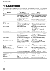
.... External effector doesn't work . TROUBLESHOOTING TROUBLESHOOTING Incorrect operations are dirty. ÷ The rear panel master output attenuator switch (MASTER ATT) is set to -12 dB, etc. ÷ The rear panel's MIC SIGNAL switch is set to [CUT]. ÷ The digital output sampling frequency (fs) does not match the specifications of the connected component. ÷ Master output level is too high. ÷ Input level is too high. ÷ CROSS FADER ASSIGN switch setting ([A], [THRU], [B]) is incorrect. ÷ The FADER START button is set to OFF. ÷ Rear panel CONTROL jack...
.... External effector doesn't work . TROUBLESHOOTING TROUBLESHOOTING Incorrect operations are dirty. ÷ The rear panel master output attenuator switch (MASTER ATT) is set to -12 dB, etc. ÷ The rear panel's MIC SIGNAL switch is set to [CUT]. ÷ The digital output sampling frequency (fs) does not match the specifications of the connected component. ÷ Master output level is too high. ÷ Input level is too high. ÷ CROSS FADER ASSIGN switch setting ([A], [THRU], [B]) is incorrect. ÷ The FADER START button is set to OFF. ÷ Rear panel CONTROL jack...
Owner's Manual
Page 23
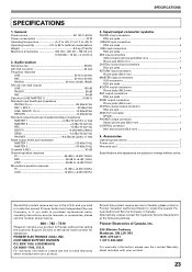
.... SPECIFICATIONS SPECIFICATIONS 1. Accessories Operating Instructions 1 Power cord 1 Warranty card 1 Specifications and appearance are subject to 85 % (without condensation) Weight 8.0 kg (17.64 lb) Maximum dimensions 320 (W) × 381 (D) × 108 (H) mm 12-5/8 (W) × 15 (D) × 4-1/4 (H) in the U.S.A. and you wish to locate the nearest Pioneer Authorized Independent Service Company, or if you wish to purchase replacement parts, operating instructions, service manuals, or accessories, please call the number shown...
.... SPECIFICATIONS SPECIFICATIONS 1. Accessories Operating Instructions 1 Power cord 1 Warranty card 1 Specifications and appearance are subject to 85 % (without condensation) Weight 8.0 kg (17.64 lb) Maximum dimensions 320 (W) × 381 (D) × 108 (H) mm 12-5/8 (W) × 15 (D) × 4-1/4 (H) in the U.S.A. and you wish to locate the nearest Pioneer Authorized Independent Service Company, or if you wish to purchase replacement parts, operating instructions, service manuals, or accessories, please call the number shown...
Owner's Manual
Page 24
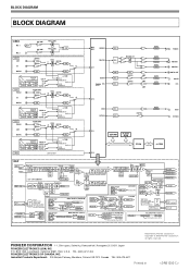
... BPM BEAT detect EFFECTS [MIC] [MIC] MIC Data Send Return MIC [MIC] Filter Talk Over On/Off CHx CROSS Fader Curve (3-posi.) EFFECT CH SELECT CH 1-4 CF_A/B MIC Master Return In BEAT EFFECT (SND/RTN) Send Out Return Level Cable Check No Cable Effect SW. CD/DIGITAL LINE CD CD LINE DIGITAL DIGITAL LINE LINE CD CD DIGITAL CH 2 PHONO CD PHONO AMP. MASTER D/A MUTE MUTE CH 1 SRC BOOTH D/A DSP REC D/A DIT BUFFER BUFFER AMP. MONO SPLIT/STEREO SW. Level H. Copyright © 2005 Pioneer Corporation. P.O. BLOCK DIAGRAM BLOCK DIAGRAM MIC MIC 1 MIC 2 MIC AMP MIC 1 LEVEL...
... BPM BEAT detect EFFECTS [MIC] [MIC] MIC Data Send Return MIC [MIC] Filter Talk Over On/Off CHx CROSS Fader Curve (3-posi.) EFFECT CH SELECT CH 1-4 CF_A/B MIC Master Return In BEAT EFFECT (SND/RTN) Send Out Return Level Cable Check No Cable Effect SW. CD/DIGITAL LINE CD CD LINE DIGITAL DIGITAL LINE LINE CD CD DIGITAL CH 2 PHONO CD PHONO AMP. MASTER D/A MUTE MUTE CH 1 SRC BOOTH D/A DSP REC D/A DIT BUFFER BUFFER AMP. MONO SPLIT/STEREO SW. Level H. Copyright © 2005 Pioneer Corporation. P.O. BLOCK DIAGRAM BLOCK DIAGRAM MIC MIC 1 MIC 2 MIC AMP MIC 1 LEVEL...


