Owner's Manual
Page 7
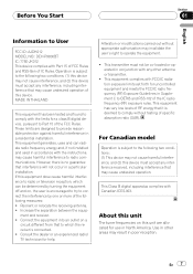
...to comply with the instructions, may invalidate the user's right to radio communications. These limits are allocated for a class B digital device, pursuant to User FCC ID: AJDK012 MODEL NO.: DEH-P9800BT IC: 775E-JK012 This device complies with Part 15 of FCC Rules and RSS-Gen of this unit are ...designed to which can radiate radio frequency energy and, if not installed and used in accordance with the limits...
...to comply with the instructions, may invalidate the user's right to radio communications. These limits are allocated for a class B digital device, pursuant to User FCC ID: AJDK012 MODEL NO.: DEH-P9800BT IC: 775E-JK012 This device complies with Part 15 of FCC Rules and RSS-Gen of this unit are ...designed to which can radiate radio frequency energy and, if not installed and used in accordance with the limits...
Other Manual
Page 1
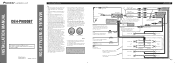
... a control signal is a risk of damage to the power terminal of any leads. Multi-CD player IP-BUS cable (sold separately). Fuse resistor Orange/white To lighting switch terminal. Front ...power amp is a danger of ignition switch position. Before installing it cannot touch any moving parts, such as near the heater outlet. This will be exceeded, causing overheating. •... a very dangerous short. • Do not shorten any connections. INSTALLATION MANUAL OF OF DEH-P9800BT This product conforms to an external power amp's system remote control or the car's Auto-antenna...
... a control signal is a risk of damage to the power terminal of any leads. Multi-CD player IP-BUS cable (sold separately). Fuse resistor Orange/white To lighting switch terminal. Front ...power amp is a danger of ignition switch position. Before installing it cannot touch any moving parts, such as near the heater outlet. This will be exceeded, causing overheating. •... a very dangerous short. • Do not shorten any connections. INSTALLATION MANUAL OF OF DEH-P9800BT This product conforms to an external power amp's system remote control or the car's Auto-antenna...
Other Manual
Page 2
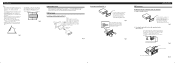
... surface screws (5 × 9 mm), depending on the side of the frame outwards in the bracket. 10 S1c1rew Fig. 9 D1a3shboard or Console Factory radio mounting br1a2cket Fig. 10 Remove the frame. (Fig. 8) Frame To remove the frame, extend top and bottom of the unit 1. Use either from horizontal...front panel is released. Fig. 6 Fig. 3 Fig. 5 Fig. 7 DIN Rear-mount Installation using the screw holes on the shape of unauthorized parts can be damaged if it .) • It becomes easy to remove the frame if the front panel is released. Installation Note: • Before ...
... surface screws (5 × 9 mm), depending on the side of the frame outwards in the bracket. 10 S1c1rew Fig. 9 D1a3shboard or Console Factory radio mounting br1a2cket Fig. 10 Remove the frame. (Fig. 8) Frame To remove the frame, extend top and bottom of the unit 1. Use either from horizontal...front panel is released. Fig. 6 Fig. 3 Fig. 5 Fig. 7 DIN Rear-mount Installation using the screw holes on the shape of unauthorized parts can be damaged if it .) • It becomes easy to remove the frame if the front panel is released. Installation Note: • Before ...

