Service Manual
Page 1
... employed in Japan PCB CONNECTION DIAGRAM 34 5. P.O.Box 1760, Long Beach, CA 90801-1760 U.S.A. Service DEH-P300/X1N/UC Manual MULTI-CD CONTROL HIGH POWER CD PLAYER WITH FM/AM TUNER DEH-P300 DEH-P3000 X1N/UC DEH-P200 X1N/UC ORDER NO. OPERATIONS AND SPECIFICATIONS 71 PIONEER ELECTRONIC CORPORATION 4-1, Meguro 1-Chome, Meguro-ku, Tokyo 153-8654, Japan...
... employed in Japan PCB CONNECTION DIAGRAM 34 5. P.O.Box 1760, Long Beach, CA 90801-1760 U.S.A. Service DEH-P300/X1N/UC Manual MULTI-CD CONTROL HIGH POWER CD PLAYER WITH FM/AM TUNER DEH-P300 DEH-P3000 X1N/UC DEH-P200 X1N/UC ORDER NO. OPERATIONS AND SPECIFICATIONS 71 PIONEER ELECTRONIC CORPORATION 4-1, Meguro 1-Chome, Meguro-ku, Tokyo 153-8654, Japan...
Service Manual
Page 2
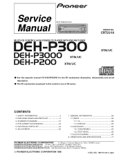
... 19 1 12 20 17 14 2 you are known to the state of California to perform the repair of the product and may void the warranty. DEH-P300,P3000,P200 - Please checking the grating after changing the service pickup unit(see page 54). During replacement, handling precautions shall be destroyed when a connector is plugged...
... 19 1 12 20 17 14 2 you are known to the state of California to perform the repair of the product and may void the warranty. DEH-P300,P3000,P200 - Please checking the grating after changing the service pickup unit(see page 54). During replacement, handling precautions shall be destroyed when a connector is plugged...
Service Manual
Page 3
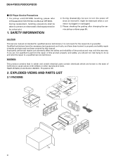
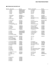
... Box 20-1 Owner's Manual 20-2 Installation Manual * 20-3 Warranty Card DEH-P300/X1N/UC CHG3645 CHL3645 CRD2822 CRD2823 CRY1070 * 20-5 Card Not used - DEH-P3000/X1N/UC CHG3644 CHL3644 CRD2820 CRD2821 Not used DEH-P200/X1N/UC CHG3658 CHL3658 CRD2822 CRD2850 CRY1070 ARY1048 Not used Part No....LIST Mark No. Description 1 Cord Assy * 2 Accessory Assy 3 Spring 4 Screw Assy 5 Screw Part No. Owner's Manual Model DEH-P300/X1N/UC, DEH-P200/X1N/UC DEH-P3000/X1N/UC - CDE5769 CEA2395 CBH1650 CEA2396 CBA1002 Mark No. Description 16 Protector 17 Protector 18 19 Case Assy 20-1 Owner's Manual Part...
... Box 20-1 Owner's Manual 20-2 Installation Manual * 20-3 Warranty Card DEH-P300/X1N/UC CHG3645 CHL3645 CRD2822 CRD2823 CRY1070 * 20-5 Card Not used - DEH-P3000/X1N/UC CHG3644 CHL3644 CRD2820 CRD2821 Not used DEH-P200/X1N/UC CHG3658 CHL3658 CRD2822 CRD2850 CRY1070 ARY1048 Not used Part No....LIST Mark No. Description 1 Cord Assy * 2 Accessory Assy 3 Spring 4 Screw Assy 5 Screw Part No. Owner's Manual Model DEH-P300/X1N/UC, DEH-P200/X1N/UC DEH-P3000/X1N/UC - CDE5769 CEA2395 CBH1650 CEA2396 CBA1002 Mark No. Description 16 Protector 17 Protector 18 19 Case Assy 20-1 Owner's Manual Part...

Service Manual
Page 5
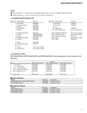
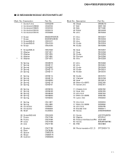
... CNV5570 CNV5571 91 Grille Unit 92 Case Unit 93 Screw 94 95 Cushion CXB3493 CXB4033 ISS26P055FUC CNM6373 5 Description 1 Screw 2 Screw 3 Screw 4 Screw 5 Cable Part No. DEH-P300,P3000,P200 -
... CNV5570 CNV5571 91 Grille Unit 92 Case Unit 93 Screw 94 95 Cushion CXB3493 CXB4033 ISS26P055FUC CNM6373 5 Description 1 Screw 2 Screw 3 Screw 4 Screw 5 Cable Part No. DEH-P300,P3000,P200 -
Service Manual
Page 7
... Module 89 Lighting Conductor 90 Connector CNM6026 CXK5200 CNV5570 CNV5571 91 Grille Unit 92 Case Unit 93 Screw 94 95 Cushion CXB3492 CXB4033 ISS26P055FUC CNM6373 7 DEH-P300,P3000,P200 -
... Module 89 Lighting Conductor 90 Connector CNM6026 CXK5200 CNV5570 CNV5571 91 Grille Unit 92 Case Unit 93 Screw 94 95 Cushion CXB3492 CXB4033 ISS26P055FUC CNM6373 7 DEH-P300,P3000,P200 -

Service Manual
Page 9
DEH-P300,P3000,P200 - Description 51 Bracket 52 Holder 53 Cover 54 Panel 55 Arm Part No. CNC6791 CNC8042 CNM6276 CNS5355 CNV4692 56 Arm 57 Arm 58 Screw ...
DEH-P300,P3000,P200 - Description 51 Bracket 52 Holder 53 Cover 54 Panel 55 Arm Part No. CNC6791 CNC8042 CNM6276 CNS5355 CNV4692 56 Arm 57 Arm 58 Screw ...
Service Manual
Page 11
... CBH2080 CBH2118 CBH2161 CBH2163 CBH2189 CBH2249 CBH2260 CBH2262 CBL1367 CBL1369 CDE5531 CDE5532 CLA3304 CBA1458 CNC7544 CNC7545 CNC7546 CNC7739 CNC7798 CNC8090 CNM3315 CNM6170 CNM6204 Mark No. DEH-P300,P3000,P200 - CD MECHANISM MODULE SECTION PARTS LIST Mark No.
... CBH2080 CBH2118 CBH2161 CBH2163 CBH2189 CBH2249 CBH2260 CBH2262 CBL1367 CBL1369 CDE5531 CDE5532 CLA3304 CBA1458 CNC7544 CNC7545 CNC7546 CNC7739 CNC7798 CNC8090 CNM3315 CNM6170 CNM6204 Mark No. DEH-P300,P3000,P200 - CD MECHANISM MODULE SECTION PARTS LIST Mark No.
Service Manual
Page 12
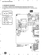
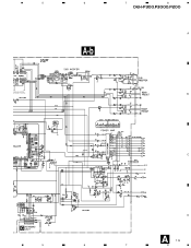
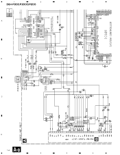
1 2 3 4 DEH-P300,P3000,P200 3. Large size A-a A-b SCH diagram A A-a IP BUS IN 4.3V 4.3V 4.3V 4.3V 4.3V A-a A-b Guide page B A-a A-b Detailed page IP BUS DRIVER 4.3V 4.3V 4.3V SO EL 4.3V 4.3V B DE C ANTENNA CABLE D A 12 1 2 3 VD REGULATOR 4 SCHEMATIC DIAGRAM 3.1 OVERALL CONNECTION DIAGRAM(GUIDE PAGE)(DEH-P300/X1N/UC) A Note: When ordering service parts, be sure to refer to "EXPLODED VIEWS AND PARTS LIST" or "ELECTRICAL PARTS LIST".
1 2 3 4 DEH-P300,P3000,P200 3. Large size A-a A-b SCH diagram A A-a IP BUS IN 4.3V 4.3V 4.3V 4.3V 4.3V A-a A-b Guide page B A-a A-b Detailed page IP BUS DRIVER 4.3V 4.3V 4.3V SO EL 4.3V 4.3V B DE C ANTENNA CABLE D A 12 1 2 3 VD REGULATOR 4 SCHEMATIC DIAGRAM 3.1 OVERALL CONNECTION DIAGRAM(GUIDE PAGE)(DEH-P300/X1N/UC) A Note: When ordering service parts, be sure to refer to "EXPLODED VIEWS AND PARTS LIST" or "ELECTRICAL PARTS LIST".
Service Manual
Page 13
5 6 4.3V 4.3V 4.3V 4.3V URCE SELECTOR, ECTRONIC VOLUME 4.3V 4.2V 1.8V 4.2V A-b 4.2V RESET 7 8 DEH-P300,P3000,P200 A B CEK1136 CEK1014 C D C A 13 5 6 7 8
5 6 4.3V 4.3V 4.3V 4.3V URCE SELECTOR, ECTRONIC VOLUME 4.3V 4.2V 1.8V 4.2V A-b 4.2V RESET 7 8 DEH-P300,P3000,P200 A B CEK1136 CEK1014 C D C A 13 5 6 7 8
Service Manual
Page 14
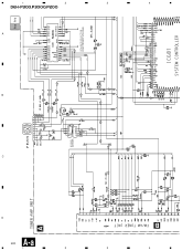
4 3 2 1 14 A-a A B D C B IP BUS IN IP BUS DRIVER A-a A-b 4.3V 4.3V 4.3V 4.3V 4.3V 4.3V 4.3V 4.3V 4.3V 4.3V 4.3V 4.3V SOURCE SELECTOR, ELECTRONIC VOLUME 4.3V 4.3V A DEH-P300,P3000,P200 4 3 2 1
4 3 2 1 14 A-a A B D C B IP BUS IN IP BUS DRIVER A-a A-b 4.3V 4.3V 4.3V 4.3V 4.3V 4.3V 4.3V 4.3V 4.3V 4.3V 4.3V 4.3V SOURCE SELECTOR, ELECTRONIC VOLUME 4.3V 4.3V A DEH-P300,P3000,P200 4 3 2 1
Service Manual
Page 20
4 3 2 1 20 A-a A B D C B IP BUS IN IP BUS DRIVER A-a A-b 4.3V 4.3V 4.3V 4.3V 4.3V 4.3V 4.3V 4.3V 4.3V 4.3V 4.3V 4.3V SOURCE SELECTOR, ELECTRONIC VOLUME 4.3V 4.3V A DEH-P300,P3000,P200 4 3 2 1
4 3 2 1 20 A-a A B D C B IP BUS IN IP BUS DRIVER A-a A-b 4.3V 4.3V 4.3V 4.3V 4.3V 4.3V 4.3V 4.3V 4.3V 4.3V 4.3V 4.3V SOURCE SELECTOR, ELECTRONIC VOLUME 4.3V 4.3V A DEH-P300,P3000,P200 4 3 2 1
Service Manual
Page 24
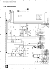
F0 FM 0dBf F65 FM 65dBf F125 FM A0 AM A74 AM A125 AM 125dBf 0dBµ 74dBµ 125dBµ KV1410(23) C D B 24 1 2 3 4 1 2 DEH-P300,P3000,P200 3.3 FM/AM TUNER UNIT A B B 3 4 A Voltage of IC Terminals Mark Band Input Level None - -
F0 FM 0dBf F65 FM 65dBf F125 FM A0 AM A74 AM A125 AM 125dBf 0dBµ 74dBµ 125dBµ KV1410(23) C D B 24 1 2 3 4 1 2 DEH-P300,P3000,P200 3.3 FM/AM TUNER UNIT A B B 3 4 A Voltage of IC Terminals Mark Band Input Level None - -

Service Manual
Page 29
5 6 7 8 DEH-P300,P3000,P200 A SWITCHES: CONTROL UNIT S801 : HOME SWITCH.....ON-OFF S802 : CLAMP SWITCH....ON-OFF The underlined indicates the switch position. B C A CN681 D D 29 5 6 7 8
5 6 7 8 DEH-P300,P3000,P200 A SWITCHES: CONTROL UNIT S801 : HOME SWITCH.....ON-OFF S802 : CLAMP SWITCH....ON-OFF The underlined indicates the switch position. B C A CN681 D D 29 5 6 7 8
Service Manual
Page 30
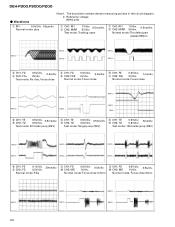
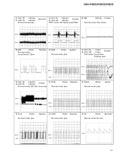
...: Focus close 6 CH1: FE 7 CH2: XSI 0.5V/div. 1ms/div. 2V/div. Normal mode: play 1 CH1: RFI 2 CH2: MIRR 1V/div. 0.5ms/div. 5V/div. DEH-P300,P3000,P200 - Waveforms Note:1. The encircled numbers denote measuring pointes in the circuit diagram. 2. Normal mode: Focus close REFO → REFO → REFO → REFO →...
...: Focus close 6 CH1: FE 7 CH2: XSI 0.5V/div. 1ms/div. 2V/div. Normal mode: play 1 CH1: RFI 2 CH2: MIRR 1V/div. 0.5ms/div. 5V/div. DEH-P300,P3000,P200 - Waveforms Note:1. The encircled numbers denote measuring pointes in the circuit diagram. 2. Normal mode: Focus close REFO → REFO → REFO → REFO →...
Service Manual
Page 31
...; 8 CH1: TE 6 CH2: FE 0.5V/div. 0.5V/div. 0.2s/div. $ PLCK 2V/div. 0.5µs/div. Normal mode: play REFO → REFO → % SCKO 2V/div. DEH-P300,P3000,P200 8 CH1: TE 0.2V/div. 9 CH2: TD 0.2V/div. Normal mode: Long Search (12cm) 10ms/div. @ EFM 1V/div. 5µs/div. REFO → REFO →...
...; 8 CH1: TE 6 CH2: FE 0.5V/div. 0.5V/div. 0.2s/div. $ PLCK 2V/div. 0.5µs/div. Normal mode: play REFO → REFO → % SCKO 2V/div. DEH-P300,P3000,P200 8 CH1: TE 0.2V/div. 9 CH2: TD 0.2V/div. Normal mode: Long Search (12cm) 10ms/div. @ EFM 1V/div. 5µs/div. REFO → REFO →...

Service Manual
Page 32
DEH-P300,P3000,P200 ( CH1: R OUT 1V/div. ) CH2: L OUT 1V/div. 0.2ms/div. 6 CH1: FE 3 CH2: FD 0.2V/div. 0.5V/div. 1ms/div. 8 CH1: TE 9 CH2: TD 0....
DEH-P300,P3000,P200 ( CH1: R OUT 1V/div. ) CH2: L OUT 1V/div. 0.2ms/div. 6 CH1: FE 3 CH2: FD 0.2V/div. 0.5V/div. 1ms/div. 8 CH1: TE 9 CH2: TD 0....
Service Manual
Page 34
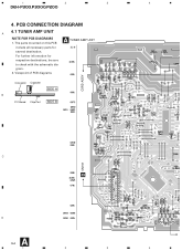
PCB CONNECTION DIAGRAM 4.1 TUNER AMP UNIT A NOTE FOR PCB DIAGRAMS 1. gram. 2. 1 2 3 4 DEH-P300,P3000,P200 4. For further information for several destination. The parts mounted on this PCB A TUNER AMP UNIT include all necessary parts for respective destinations, be sure to check with the schematic dia- Viewpoint of PCB diagrams CORD ASSY Connector Capacitor SIDE A B P.C.Board Chip Part SIDE B C D CN701 D A 34 1 2 3 4
PCB CONNECTION DIAGRAM 4.1 TUNER AMP UNIT A NOTE FOR PCB DIAGRAMS 1. gram. 2. 1 2 3 4 DEH-P300,P3000,P200 4. For further information for several destination. The parts mounted on this PCB A TUNER AMP UNIT include all necessary parts for respective destinations, be sure to check with the schematic dia- Viewpoint of PCB diagrams CORD ASSY Connector Capacitor SIDE A B P.C.Board Chip Part SIDE B C D CN701 D A 34 1 2 3 4
Service Manual
Page 44
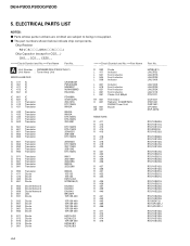
...,RS1/__S___J Chip Capacitor (except for CQS.....) CKS....., CCS....., CSZS..... =====Circuit Symbol and No.===Part Name Part No A Unit Number : CWM6082(DEH-P300/X1N/UC) Unit Name : Tuner Amp Unit MISCELLANEOUS IC 411 IC IC 451 IC IC 471 IC IC 472 IC IC 551 IC CA0008AM PML003AM...RS1/10S223J RS1/10S223J RS1/10S223J RS1/10S223J RS1/8S473J RD1/4PU221J RD1/4PU221J RS1/10S183J RS1/10S183J RS1/10S183J RS1/10S183J RS1/10S472J 44 DEH-P300,P3000,P200 5. The part numbers shown below indicate chip components. Parts whose parts numbers are omitted are subject to being not supplied. - ...
...,RS1/__S___J Chip Capacitor (except for CQS.....) CKS....., CCS....., CSZS..... =====Circuit Symbol and No.===Part Name Part No A Unit Number : CWM6082(DEH-P300/X1N/UC) Unit Name : Tuner Amp Unit MISCELLANEOUS IC 411 IC IC 451 IC IC 471 IC IC 472 IC IC 551 IC CA0008AM PML003AM...RS1/10S223J RS1/10S223J RS1/10S223J RS1/10S223J RS1/8S473J RD1/4PU221J RD1/4PU221J RS1/10S183J RS1/10S183J RS1/10S183J RS1/10S183J RS1/10S472J 44 DEH-P300,P3000,P200 5. The part numbers shown below indicate chip components. Parts whose parts numbers are omitted are subject to being not supplied. - ...
Service Manual
Page 52
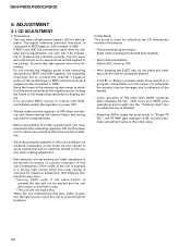
... stabilize. • Since the protective systems in the unit's software are rendered inoperative in test mode, be ejected and the unit will not load a disc. DEH-P300,P3000,P200 6. If REFO and GND are brought into the "Tracking close" status when the key is connected to further adjustments and measurements after releasing the...
... stabilize. • Since the protective systems in the unit's software are rendered inoperative in test mode, be ejected and the unit will not load a disc. DEH-P300,P3000,P200 6. If REFO and GND are brought into the "Tracking close" status when the key is connected to further adjustments and measurements after releasing the...
Service Manual
Page 82
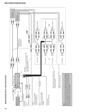
... speaker ≠ + Front speaker ≠ Right + Rear speaker ≠ + Rear speaker ≠ Red To electric terminal controlled by ignition switch (12 V DC) ON/OFF. DEH-P3000/X1N/UC, DEH-P200/X1N/UC Antenna jack This Product Multi-CD player (sold separately). Brown White/yellow Fuse holder Fuse resistor Front output Fuse Blue/white...) See the section "DFS Alarm Installation". the leads that serves the same function. + Rear speaker ≠ Connecting cords with power regardless of ignition switch position. DEH-P300,P3000,P200 82 -
... speaker ≠ + Front speaker ≠ Right + Rear speaker ≠ + Rear speaker ≠ Red To electric terminal controlled by ignition switch (12 V DC) ON/OFF. DEH-P3000/X1N/UC, DEH-P200/X1N/UC Antenna jack This Product Multi-CD player (sold separately). Brown White/yellow Fuse holder Fuse resistor Front output Fuse Blue/white...) See the section "DFS Alarm Installation". the leads that serves the same function. + Rear speaker ≠ Connecting cords with power regardless of ignition switch position. DEH-P300,P3000,P200 82 -


