Owner's Manual
Page 2
...setting your equipment at a safe level BEFORE your own security and convenience, be installed and operated keeping the radiator at least 20 cm or more away from contact ...appropriate authorization may cause undesired operation. For Canadian model FCC ID: AJDK033 MODEL NO.: DEH-7300BT/DEH-73BT IC: 775E-K033 This equipment complies with ignition switch on/off , it deemed ... CAUTIONs in poor reception. This equipment has very low levels of headphones may result in this PIONEER product. This device complies with liquids. ! Also, damage to hear outside sounds. ! Use...
...setting your equipment at a safe level BEFORE your own security and convenience, be installed and operated keeping the radiator at least 20 cm or more away from contact ...appropriate authorization may cause undesired operation. For Canadian model FCC ID: AJDK033 MODEL NO.: DEH-7300BT/DEH-73BT IC: 775E-K033 This equipment complies with ignition switch on/off , it deemed ... CAUTIONs in poor reception. This equipment has very low levels of headphones may result in this PIONEER product. This device complies with liquids. ! Also, damage to hear outside sounds. ! Use...
Owner's Manual
Page 5
...if the battery is selected on the monitor, using these advanced operations. If the battery leaks, wipe the remote control completely clean and install a new battery. ! Advanced operations that require attention such as dialing numbers on the cellular phone, hands-free phoning may not be ...or AM) is on the kind of children. Switching the display Selecting the desired text information 1 Press . Batteries (battery pack or batteries installed) must set up the unit for a month or longer. ! Do not store the battery with governmental regulations or environmental public institutions' ...
...if the battery is selected on the monitor, using these advanced operations. If the battery leaks, wipe the remote control completely clean and install a new battery. ! Advanced operations that require attention such as dialing numbers on the cellular phone, hands-free phoning may not be ...or AM) is on the kind of children. Switching the display Selecting the desired text information 1 Press . Batteries (battery pack or batteries installed) must set up the unit for a month or longer. ! Do not store the battery with governmental regulations or environmental public institutions' ...
Owner's Manual
Page 11
... of an external power amp. Disconnect the negative terminal of the battery before transferring the unit to 8 W (impedance value). When installing this unit in battery drain. S/W UPDATE (updating the software) This function is displayed. To prevent a short-circuit, overheating or ...(output value) and between 4 W to other operations, but the clock display appears again after 25 seconds. Section Operating this unit Installation 03 English Bluetooth telephone data can display the system versions of this unit and of Bluetooth module. 1 Press M.C. To protect personal information...
... of an external power amp. Disconnect the negative terminal of the battery before transferring the unit to 8 W (impedance value). When installing this unit in battery drain. S/W UPDATE (updating the software) This function is displayed. To prevent a short-circuit, overheating or ...(output value) and between 4 W to other operations, but the clock display appears again after 25 seconds. Section Operating this unit Installation 03 English Bluetooth telephone data can display the system versions of this unit and of Bluetooth module. 1 Press M.C. To protect personal information...
Owner's Manual
Page 12
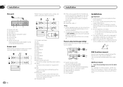
... a result of the power amp or auto-antenna relay control terminal (max. 300 mA 12 V DC). it may interfere with the vehicle. If there is installed at an angle of this may cause injury to the vehicle. ! L 1 R 2 3 4 6 8 F 7 9 &#... amplifier. 1 3 2 4 5 5 3 1 2 6 7 7 Installation Important ! Do not install this unit. With a 2 speaker system, do not connect anything to terminal controlled by ignition switch (12 V DC). it may cause malfunctions...
... a result of the power amp or auto-antenna relay control terminal (max. 300 mA 12 V DC). it may interfere with the vehicle. If there is installed at an angle of this may cause injury to the vehicle. ! L 1 R 2 3 4 6 8 F 7 9 &#... amplifier. 1 3 2 4 5 5 3 1 2 6 7 7 Installation Important ! Do not install this unit. With a 2 speaker system, do not connect anything to terminal controlled by ignition switch (12 V DC). it may cause malfunctions...
Owner's Manual
Page 13
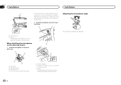
...truss (5 mm × 8 mm) or flush sur- When reattaching the trim ring, point the side with the supplied screw. Installing the microphone CAUTION It is installed securely in place. Releasing the front panel allows easier ac- face (5 mm × 9 mm) screws, depending on the ... each side. 1 3 2 1 Screw 2 Mounting bracket 3 Dashboard or console ! When installing the microphone on the sun visor 1 Install the microphone on the microphone clip. 1 2 1 Screw 1 Microphone 2 Microphone clip 1 2 Install the microphone clip on the bracket screw holes. With the sun visor up the voice of ...
...truss (5 mm × 8 mm) or flush sur- When reattaching the trim ring, point the side with the supplied screw. Installing the microphone CAUTION It is installed securely in place. Releasing the front panel allows easier ac- face (5 mm × 9 mm) screws, depending on the ... each side. 1 3 2 1 Screw 2 Mounting bracket 3 Dashboard or console ! When installing the microphone on the sun visor 1 Install the microphone on the microphone clip. 1 2 1 Screw 1 Microphone 2 Microphone clip 1 2 Install the microphone clip on the bracket screw holes. With the sun visor up the voice of ...
Owner's Manual
Page 14
... 3 Clamp Use separately sold clamps to secure the lead where necessary inside the vehicle. To detach the micro- When installing the microphone on the steering column 1 Install the microphone on the microphone clip. 1 2 2 3 Adjusting the microphone angle The microphone angle can be adjusted. ...3 4 1 Microphone 2 Microphone base 3 Microphone clip 4 Fit the microphone lead into the groove. 1 Double-sided tape 2 Install the microphone clip on the steering column. 1 2 1 Microphone clip 2 Clamp Use separately sold clamps to secure the lead where necessary inside the ...
... 3 Clamp Use separately sold clamps to secure the lead where necessary inside the vehicle. To detach the micro- When installing the microphone on the steering column 1 Install the microphone on the microphone clip. 1 2 2 3 Adjusting the microphone angle The microphone angle can be adjusted. ...3 4 1 Microphone 2 Microphone base 3 Microphone clip 4 Fit the microphone lead into the groove. 1 Double-sided tape 2 Install the microphone clip on the steering column. 1 2 1 Microphone clip 2 Clamp Use separately sold clamps to secure the lead where necessary inside the ...


