
Owner's Manual
Page 1
... Ground side Parking brake switch Fig. 2 To protect the wiring, wrap adhesive tape around them where they have the same function. Red To electric terminal controlled by cutting the insulation of the power supply lead of both products and connect cords that have an ACC (accessory) position on connecting the power amp and other units, then make connections correctly. • Secure the wiring with cable clamps or adhesive tape. Black (ground...
... Ground side Parking brake switch Fig. 2 To protect the wiring, wrap adhesive tape around them where they have the same function. Red To electric terminal controlled by cutting the insulation of the power supply lead of both products and connect cords that have an ACC (accessory) position on connecting the power amp and other units, then make connections correctly. • Secure the wiring with cable clamps or adhesive tape. Black (ground...
Owner's Manual
Page 2
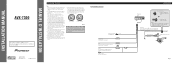
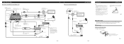
... there is all connected up properly, and the unit and the system work properly. • Use only the parts included with the unit to the DVD player.) Fig. 3 When Connecting the Navigation Unit To audio inputs of car stereo To audio outputs RCA cable (sold separately) Voice guidance speaker (supplied) This product 3m Red Yellow (VIDEO INPUT) 15 cm 3m 20 pin cable Red (supplied) Fig. 4 Installation Note: • Before finally installing the unit, connect the wiring temporarily, making sure it .) Fig...
... there is all connected up properly, and the unit and the system work properly. • Use only the parts included with the unit to the DVD player.) Fig. 3 When Connecting the Navigation Unit To audio inputs of car stereo To audio outputs RCA cable (sold separately) Voice guidance speaker (supplied) This product 3m Red Yellow (VIDEO INPUT) 15 cm 3m 20 pin cable Red (supplied) Fig. 4 Installation Note: • Before finally installing the unit, connect the wiring temporarily, making sure it .) Fig...

Owner's Manual
Page 3
...Factory radio mounting bra1c2ket Fig. 11 S1c1rew D13ashboard or Console Fig. 12 Installing the Voice Guidance Speaker Precaution: • Do not install on the side of this case, stick conceal tape on each side. Remove the frame. (Fig. 10) Fig. 9 Frame Pull out to direct sunlight. Fastening the unit to the thickness of the remote control signal. Fastening the unit...) DIN Rear-mount Installation using the top and bottom tabs. Installation 2. In this product become aligned (are fitted), and tighten the screws at 2 places on parts that protrude from the dashboard. Use any of...
...Factory radio mounting bra1c2ket Fig. 11 S1c1rew D13ashboard or Console Fig. 12 Installing the Voice Guidance Speaker Precaution: • Do not install on the side of this case, stick conceal tape on each side. Remove the frame. (Fig. 10) Fig. 9 Frame Pull out to direct sunlight. Fastening the unit to the thickness of the remote control signal. Fastening the unit...) DIN Rear-mount Installation using the top and bottom tabs. Installation 2. In this product become aligned (are fitted), and tighten the screws at 2 places on parts that protrude from the dashboard. Use any of...

Other Manual
Page 2
... higher volumes of your musical enjoyment. tion. We Want You Listening For A Lifetime Used wisely, your new sound equipment will help to get the most importantly, without affecting your equipment offers. i To establish a safe level: • Start your volume control at a safe level. After all, we want you to prevent hearing damage or loss in front of speakers...
... higher volumes of your musical enjoyment. tion. We Want You Listening For A Lifetime Used wisely, your new sound equipment will help to get the most importantly, without affecting your equipment offers. i To establish a safe level: • Start your volume control at a safe level. After all, we want you to prevent hearing damage or loss in front of speakers...
Other Manual
Page 3
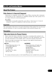
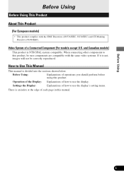
...be sure to this number on the bottom of a Connected Component This product is not, images will not be sure components are compatible with the same video systems. If it is compatible with the PAL ...repair without advance contact. 7 U.S.A. In case the necessary information is incompatible with the NTSC system. For your product. CUSTOMER SERVICE DEPARTMENT P.O. and Canadian Models About This Product Video System of this device is located on the enclosed warranty card. Pioneer Electronics Service, Inc. When connecting other information. Important The serial number...
...be sure to this number on the bottom of a Connected Component This product is not, images will not be sure components are compatible with the same video systems. If it is compatible with the PAL ...repair without advance contact. 7 U.S.A. In case the necessary information is incompatible with the NTSC system. For your product. CUSTOMER SERVICE DEPARTMENT P.O. and Canadian Models About This Product Video System of this device is located on the enclosed warranty card. Pioneer Electronics Service, Inc. When connecting other information. Important The serial number...
Other Manual
Page 4
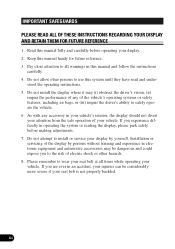
Keep this manual and follow the instructions carefully. 4. As with any of the display by yourself. Do not attempt to use this manual fully and carefully before making adjustments. 7. iii Pay close attention to safely operate the vehicle. 6. If you to wear your display by persons without training and experience in operating the system or reading the display, please park safely before operating your...
Keep this manual and follow the instructions carefully. 4. As with any of the display by yourself. Do not attempt to use this manual fully and carefully before making adjustments. 7. iii Pay close attention to safely operate the vehicle. 6. If you to wear your display by persons without training and experience in operating the system or reading the display, please park safely before operating your...

Other Manual
Page 6
... SAFEGUARDS iii - How to Adjust Picture Brightness - Precaution - Setting the Automatic Open Mode - Adjusting the Bright - About the Liquid Crystal (LCD) Screen - Be Sure to Use This Manual - Entering the Display Setting Menu - Adjusting the Hue - Contents Dear Customer i For U.S. In Case of the Display 7 Deploying the Display 7 Screen Angle Adjustment 8 Closing the Display 9 Changing the Wide Mode 10 Switching the Illumination Color (For European models 11 Switching the Video Source 12 Setting the Display 13 Operating the Setting Menu 13 - About This Product...
... SAFEGUARDS iii - How to Adjust Picture Brightness - Precaution - Setting the Automatic Open Mode - Adjusting the Bright - About the Liquid Crystal (LCD) Screen - Be Sure to Use This Manual - Entering the Display Setting Menu - Adjusting the Hue - Contents Dear Customer i For U.S. In Case of the Display 7 Deploying the Display 7 Screen Angle Adjustment 8 Closing the Display 9 Changing the Wide Mode 10 Switching the Illumination Color (For European models 11 Switching the Video Source 12 Setting the Display 13 Operating the Setting Menu 13 - About This Product...
Other Manual
Page 7
... Display: Explanations of operations you should perform before using this product, be correctly reproduced. Before Using 2 Before Using: Explanations of how to this product. When connecting other components to use the display's setting menu. There is NTSC/PAL system compatible. Video System of how to Use This Manual This manual is divided into the sections shown below. How to use the display. Settings the Display: Explanations of a Connected Component [For models...
... Display: Explanations of operations you should perform before using this product, be correctly reproduced. Before Using 2 Before Using: Explanations of how to this product. When connecting other components to use the display's setting menu. There is NTSC/PAL system compatible. Video System of how to Use This Manual This manual is divided into the sections shown below. How to use the display. Settings the Display: Explanations of a Connected Component [For models...

Other Manual
Page 8
...Adjust Picture Brightness Although the angle at the angle of use. (Refer to page 15.) 3 When first using the display, adjust the picture to a brightness that is visible to the driver. • In some countries or states the viewing of images on the display. If any of these functions, please stop your vehicle and engage the parking brake... laws, this manual handy as a reference for operating procedures and precautions. • Always keep the volume low enough for use with a video screen that allows clear visibility at which the LCD can be positioned and viewed clearly is limited...
...Adjust Picture Brightness Although the angle at the angle of use. (Refer to page 15.) 3 When first using the display, adjust the picture to a brightness that is visible to the driver. • In some countries or states the viewing of images on the display. If any of these functions, please stop your vehicle and engage the parking brake... laws, this manual handy as a reference for operating procedures and precautions. • Always keep the volume low enough for use with a video screen that allows clear visibility at which the LCD can be positioned and viewed clearly is limited...
Other Manual
Page 9
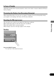
When the machine fails to operate properly, contact your dealer or nearest authorized Pioneer Service Station. Use a pen tip or other pointed instrument. 4 Preventing the Battery from Becoming Exhausted When using this product, be reset under the following conditions: When using this product for the first time after installation. When strange (incorrect) messages appear on the display. Resetting the Microprocessor The microprocessor must be sure your...
When the machine fails to operate properly, contact your dealer or nearest authorized Pioneer Service Station. Use a pen tip or other pointed instrument. 4 Preventing the Battery from Becoming Exhausted When using this product, be reset under the following conditions: When using this product for the first time after installation. When strange (incorrect) messages appear on the display. Resetting the Microprocessor The microprocessor must be sure your...

Other Manual
Page 12
... display automatically. * Installing the front panel will automatically deploy the display. (Refer to page 5.) • The automatic close/open mode will operate the display as follows. * When the ignition switch is turned OFF while the display is deployed, the display will not deploy the display. When the ignition switch is turned ON again (or turned to ACC), the display will be deployed automatically. * When using an AUDIO VISUAL MASTER UNIT, turning...
... display automatically. * Installing the front panel will automatically deploy the display. (Refer to page 5.) • The automatic close/open mode will operate the display as follows. * When the ignition switch is turned OFF while the display is deployed, the display will not deploy the display. When the ignition switch is turned ON again (or turned to ACC), the display will be deployed automatically. * When using an AUDIO VISUAL MASTER UNIT, turning...
Other Manual
Page 15
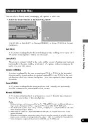
... menu setting is deleted. • When video is , giving you no sense of disparity since its proportions are the same as it may constitute an infringement on a wide screen. tings can be memorized for a component (AV) connected to the AV-BUS input. • The Wide Mode used for the AV, VTR and RGB video. The Wide Mode will appear roughened when viewed...
... menu setting is deleted. • When video is , giving you no sense of disparity since its proportions are the same as it may constitute an infringement on a wide screen. tings can be memorized for a component (AV) connected to the AV-BUS input. • The Wide Mode used for the AV, VTR and RGB video. The Wide Mode will appear roughened when viewed...
Other Manual
Page 17
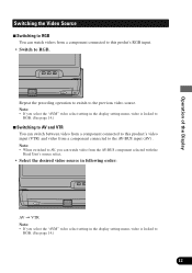
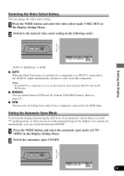
Operation of the Display Switching the Video Source 7 Switching to RGB You can watch video from the AV-BUS component selected with the Head Unit's source select. • Select the desired video source in following order: AV = VTR Note: • If you select the "AVM" video select setting in the display setting menu, video is locked to RGB. (See page 14.) 7 Switching to AV and VTR You can watch videos from a component connected to...
Operation of the Display Switching the Video Source 7 Switching to RGB You can watch video from the AV-BUS component selected with the Head Unit's source select. • Select the desired video source in following order: AV = VTR Note: • If you select the "AVM" video select setting in the display setting menu, video is locked to RGB. (See page 14.) 7 Switching to AV and VTR You can watch videos from a component connected to...
Other Manual
Page 18
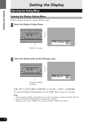
... the Display Setting Menu, if you do not perfome an operation within about 30 seconds, the Display Setting Menu is automatically canceled. • When the video source is RGB, you can not switch the "COLOR" and "HUE". 13 VSEL SET = AUTO OPEN = BRIGHT = COLOR* = HUE* = DIMMER To cancel the Display Setting Menu, press the WIDE button again for 2 seconds 2 Select the desired mode in the following order: Each press changes the Mode ... Hold...
... the Display Setting Menu, if you do not perfome an operation within about 30 seconds, the Display Setting Menu is automatically canceled. • When the video source is RGB, you can not switch the "COLOR" and "HUE". 13 VSEL SET = AUTO OPEN = BRIGHT = COLOR* = HUE* = DIMMER To cancel the Display Setting Menu, press the WIDE button again for 2 seconds 2 Select the desired mode in the following order: Each press changes the Mode ... Hold...
Other Manual
Page 19
... automatic open mode (AUTO OPEN) in the following order: AUTO = MANUAL = AVM 7 AUTO When the Head Unit source is switched to be carried out automatically, you can use this function when using the SDV-P7 with the V.SOURCE button. (Refer to page 12.) 7 AVM This prevents switching from video from a component connected to video from hitting the shift lever of the display to a component (e.g. Setting the Automatic Open Mode To prevent the display from...
... automatic open mode (AUTO OPEN) in the following order: AUTO = MANUAL = AVM 7 AUTO When the Head Unit source is switched to be carried out automatically, you can use this function when using the SDV-P7 with the V.SOURCE button. (Refer to page 12.) 7 AVM This prevents switching from video from a component connected to video from hitting the shift lever of the display to a component (e.g. Setting the Automatic Open Mode To prevent the display from...

Other Manual
Page 20
... vehicle lights are off (bright daylight) or on (dark night) respectively. Note: • The density of the display black can be adjusted within the range of "-24" to the AV-BUS input are recorded separately for the AV, VTR and RGB video. Adjusting the Color You can adjust the color of the picture. 1 Press the WIDE button and select the Bright mode (BRIGHT) in the Display Setting Menu. 2 Adjust the Color...
... vehicle lights are off (bright daylight) or on (dark night) respectively. Note: • The density of the display black can be adjusted within the range of "-24" to the AV-BUS input are recorded separately for the AV, VTR and RGB video. Adjusting the Color You can adjust the color of the picture. 1 Press the WIDE button and select the Bright mode (BRIGHT) in the Display Setting Menu. 2 Adjust the Color...

Other Manual
Page 21
... when the setting screen disappears. 1 Press the WIDE button and select the Dimmer mode (DIMMER) in accordance with the ambient brightness based on (dark night) respectively. Adjusting the Dimmer The brightness of the LCD screen can adjust the hue of a component (AV) connected to match the ambient brightness. The brightness of the picture changes from reddish to "+24" as dark conditions (blue). Note: • The display changes within...
... when the setting screen disappears. 1 Press the WIDE button and select the Dimmer mode (DIMMER) in accordance with the ambient brightness based on (dark night) respectively. Adjusting the Dimmer The brightness of the LCD screen can adjust the hue of a component (AV) connected to match the ambient brightness. The brightness of the picture changes from reddish to "+24" as dark conditions (blue). Note: • The display changes within...
Other Manual
Page 22
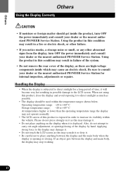
... the system. • Do not remove the rear cover of time, it as there are high-voltage components inside the product, turn OFF the power immediately and consult your dealer or the nearest authorized PIONEER Service Station. Using the product in this condition may result in possible damage to carry out angle adjustment, or opening or closing of this product is...
... the system. • Do not remove the rear cover of time, it as there are high-voltage components inside the product, turn OFF the power immediately and consult your dealer or the nearest authorized PIONEER Service Station. Using the product in this condition may result in possible damage to carry out angle adjustment, or opening or closing of this product is...
Other Manual
Page 23
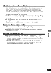
... removing dust from the cooler may cause moisture to form inside the display may be shortened. • Small black dots or white dots (bright dots) may appear on operating conditions. (Using the display at low temperatures reduces the service life of the fluorescent tube.) * When the fluorescent tube reaches the end of its useful life, the screen will be dark and the image...
... removing dust from the cooler may cause moisture to form inside the display may be shortened. • Small black dots or white dots (bright dots) may appear on operating conditions. (Using the display at low temperatures reduces the service life of the fluorescent tube.) * When the fluorescent tube reaches the end of its useful life, the screen will be dark and the image...
Other Manual
Page 24
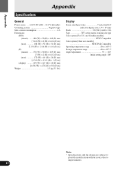
... Compatible Color system [Other area models] NTSC/PAL Compatible Operating temperature range 20 to +60° C Storage temperature range 40 to +85° C Angle Adjustment 55 - 110° Initial setting angle: 100° Note: • Specifications and the design are subject to possible modification without notice due to improvements. 19 Appendix Appendix Specifications General Power source .... 14.4 V DC (10.8 - 15.1 V allowable) Grounding...
... Compatible Color system [Other area models] NTSC/PAL Compatible Operating temperature range 20 to +60° C Storage temperature range 40 to +85° C Angle Adjustment 55 - 110° Initial setting angle: 100° Note: • Specifications and the design are subject to possible modification without notice due to improvements. 19 Appendix Appendix Specifications General Power source .... 14.4 V DC (10.8 - 15.1 V allowable) Grounding...

