Service Manual
Page 1
..., refer to the following manual(s). P.O. ARP3198 PDP-434CMX PLASMA DISPLAY PDP-434CMX PDP-43MXE1 PDP-43MXE1-S THIS MANUAL IS APPLICABLE TO THE FOLLOWING MODEL(S) AND TYPE(S). Remarks PDP-434CMX, PDP-43MXE1 PDP-43MXE1-S ARP3199 SCHEMATIC DIAGRAM, PCB CONNECTION DIAGRAM Refer to "Important symbols for video card. Model No. Model Type Power Requirement Remarks PDP-434CMX PDP-43MXE1 PDP-43MXE1-S LUC LDFK LDFK AC100 - 120V AC100...
..., refer to the following manual(s). P.O. ARP3198 PDP-434CMX PLASMA DISPLAY PDP-434CMX PDP-43MXE1 PDP-43MXE1-S THIS MANUAL IS APPLICABLE TO THE FOLLOWING MODEL(S) AND TYPE(S). Remarks PDP-434CMX, PDP-43MXE1 PDP-43MXE1-S ARP3199 SCHEMATIC DIAGRAM, PCB CONNECTION DIAGRAM Refer to "Important symbols for video card. Model No. Model Type Power Requirement Remarks PDP-434CMX PDP-43MXE1 PDP-43MXE1-S LUC LDFK LDFK AC100 - 120V AC100...
Service Manual
Page 7
...) Input Mini D-sub 15 pin (socket connector) RGB signal (G ON SYNC compatible) RGB ... 0.7 Vp-p/75 Ω/no sync. SPECIFICATIONS PLASMA DISPLAY (PDP-434CMX, PDP-43MXE1, PDP-43MXE1-S) General Light emission panel 43-inch" AC Plasma Panel 95.2 (W) x 53.6 (H) x 109.3 (diagonal) cm Number of pixels 1024 x 768 A Control RS-232C D-sub 9 pin (pin connector) COMBINATION IN/OUT Mini DIN 6 pin...
...) Input Mini D-sub 15 pin (socket connector) RGB signal (G ON SYNC compatible) RGB ... 0.7 Vp-p/75 Ω/no sync. SPECIFICATIONS PLASMA DISPLAY (PDP-434CMX, PDP-43MXE1, PDP-43MXE1-S) General Light emission panel 43-inch" AC Plasma Panel 95.2 (W) x 53.6 (H) x 109.3 (diagonal) cm Number of pixels 1024 x 768 A Control RS-232C D-sub 9 pin (pin connector) COMBINATION IN/OUT Mini DIN 6 pin...
Service Manual
Page 9
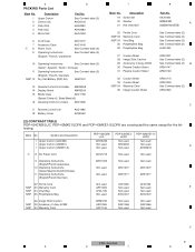
... Stick Caution 29 Accessory C.Assy 4CMX 30 Plasma Caution Sheet 31 Plasma Caution Sheet 32 33 NSP 34 35 Caution Sheet Caution Sheet Warranty Card Image Caution Sheet 8 Part No. Symbol and Description PDP-434CMX/ LUC PDP-43MXE1/ PDP-43MXE1-S/ LDFK LDFK 1 Upper Carton (434CMX) AHD3232 Not used Not used 1 Upper ...Accessory C.Assy 4CMX 34 Warranty Card ARM1240 AXX1065 ARY1146 Not used AXX1066 Not used Not used AXX1066 Not used F PDP-434CMX 9 5 6 7 8 Description 1 Upper Carton 2 Carton (43) 3 Pad (43U) 4 Pad (43L) 5 Mirror Mat 6 Part No. 5 PACKING Parts List Mark No.
... Stick Caution 29 Accessory C.Assy 4CMX 30 Plasma Caution Sheet 31 Plasma Caution Sheet 32 33 NSP 34 35 Caution Sheet Caution Sheet Warranty Card Image Caution Sheet 8 Part No. Symbol and Description PDP-434CMX/ LUC PDP-43MXE1/ PDP-43MXE1-S/ LDFK LDFK 1 Upper Carton (434CMX) AHD3232 Not used Not used 1 Upper ...Accessory C.Assy 4CMX 34 Warranty Card ARM1240 AXX1065 ARY1146 Not used AXX1066 Not used Not used AXX1066 Not used F PDP-434CMX 9 5 6 7 8 Description 1 Upper Carton 2 Carton (43) 3 Pad (43U) 4 Pad (43L) 5 Mirror Mat 6 Part No. 5 PACKING Parts List Mark No.
Service Manual
Page 63
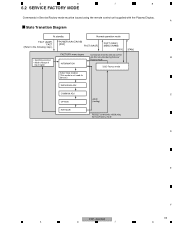
5 6 7 8 6.2 SERVICE FACTORY MODE Commands in Service/Factory mode must be issued using the remote control unit supplied with the Plasma Display. A State Transition Diagram At standby Normal operation mode FACT (AA5F) FACT (Refer to the following step.) POWER (AA1C/AA1B) [POF] FACT (AA5F) FACT (AA5F) ... mode FUNCTION CHECK (This mode is not used for service.) INDIVIDUAL ADJ COMMON ADJ C OPTION AA49 (muting) INITIALIZE RS232C commands valid during Service/Factory mode D E F PDP-434CMX 63 5 6 7 8
5 6 7 8 6.2 SERVICE FACTORY MODE Commands in Service/Factory mode must be issued using the remote control unit supplied with the Plasma Display. A State Transition Diagram At standby Normal operation mode FACT (AA5F) FACT (Refer to the following step.) POWER (AA1C/AA1B) [POF] FACT (AA5F) FACT (AA5F) ... mode FUNCTION CHECK (This mode is not used for service.) INDIVIDUAL ADJ COMMON ADJ C OPTION AA49 (muting) INITIALIZE RS232C commands valid during Service/Factory mode D E F PDP-434CMX 63 5 6 7 8

Service Manual
Page 148
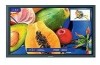
... messages. Operation panel on -screen menu. VOLUME (+/-) buttons When not indicated for use are used to select the screen size. ! When flashing, the indicator is set status. 6 Handles The plasma displays PDP-504CMX/ PDP-50MXE1/ PDP-50MXE1-S and PDP-434CMX/ PDP-43MXE1/ PDP-43MXE1-S utilize ...to indicate error When not indicated by onscreen menus, used for use in standby mode. PANEL FACILITIES MAIN UNIT A 6 B 3 - 4 7 8 9 0 = ~ ! Lights green when the plasma display is operating. D 3 Ambient light sensor This sensor measures the level of handle attachment...
... messages. Operation panel on -screen menu. VOLUME (+/-) buttons When not indicated for use are used to select the screen size. ! When flashing, the indicator is set status. 6 Handles The plasma displays PDP-504CMX/ PDP-50MXE1/ PDP-50MXE1-S and PDP-434CMX/ PDP-43MXE1/ PDP-43MXE1-S utilize ...to indicate error When not indicated by onscreen menus, used for use in standby mode. PANEL FACILITIES MAIN UNIT A 6 B 3 - 4 7 8 9 0 = ~ ! Lights green when the plasma display is operating. D 3 Ambient light sensor This sensor measures the level of handle attachment...

Service Manual
Page 149
...and off or in the factory setup. 3 RS-232C Never connect any component to these connectors without first consulting your Pioneer installation technician. F PDP-434CMX 149 5 6 7 8 Connect a speaker that has an impedance of 8 -16 Ω. Note: The video ...from the ANALOG RGB OUT (INPUT1) terminal when the main power of this connector without first consulting your Pioneer installation technician. D 7 DIGITAL RGB (INPUT2) (DVI-D jack) Use to connect a computer. 5 6 7 CONNECTION PANEL (PLASMA DISPLAY SECTION) POWER OFF ON AC IN 0 - 8 A SPEAKER 8+ ~16 L = B ~ ...
...and off or in the factory setup. 3 RS-232C Never connect any component to these connectors without first consulting your Pioneer installation technician. F PDP-434CMX 149 5 6 7 8 Connect a speaker that has an impedance of 8 -16 Ω. Note: The video ...from the ANALOG RGB OUT (INPUT1) terminal when the main power of this connector without first consulting your Pioneer installation technician. D 7 DIGITAL RGB (INPUT2) (DVI-D jack) Use to connect a computer. 5 6 7 CONNECTION PANEL (PLASMA DISPLAY SECTION) POWER OFF ON AC IN 0 - 8 A SPEAKER 8+ ~16 L = B ~ ...


