Owner's Manual
Page 5
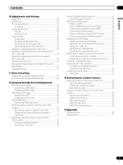
...adjustments 41 Pro Adjust 41 Sound adjustments 42 FOCUS 43 Front Surround 43 Power Control 43 Energy Save 43 No Signal off (AV mode only 43 No Operation off (AV mode only 44 Power ... a VCR or DVD recorder 52 Avoiding unwanted feedback 52 Connecting a recorder 53 Connecting other audio equipment 53 Connecting an AV receiver 53 Watching a D-VHS image 54 What is i.LINK ... recorder 56 Editing the i.LINK list 56 Setting up for i.LINK standby 57 Operating the control panel screen 57 Watching an image from a personal computer 58 Connecting a personal computer 58 Displaying an image...
...adjustments 41 Pro Adjust 41 Sound adjustments 42 FOCUS 43 Front Surround 43 Power Control 43 Energy Save 43 No Signal off (AV mode only 43 No Operation off (AV mode only 44 Power ... a VCR or DVD recorder 52 Avoiding unwanted feedback 52 Connecting a recorder 53 Connecting other audio equipment 53 Connecting an AV receiver 53 Watching a D-VHS image 54 What is i.LINK ... recorder 56 Editing the i.LINK list 56 Setting up for i.LINK standby 57 Operating the control panel screen 57 Watching an image from a personal computer 58 Connecting a personal computer 58 Displaying an image...

Owner's Manual
Page 7
... remaining on the Plasma Display continuously over several... After-image lagging due to help prevent damage from screen burning (see page 43). After-image (lag image) due to burning Avoid displaying the same image ..., but they had been displayed. 2. About operations through i.LINK PIONEER shall not always assure normal video/audio recording or playback when a D-VHS is displayed continuously for several ...CART COMBINATION SHOULD BE MOVED WITH THE CARE. Important User Guidance Information 01 English Panel sticking and after-image lag • Displaying the same images such as still ...
... remaining on the Plasma Display continuously over several... After-image lagging due to help prevent damage from screen burning (see page 43). After-image (lag image) due to burning Avoid displaying the same image ..., but they had been displayed. 2. About operations through i.LINK PIONEER shall not always assure normal video/audio recording or playback when a D-VHS is displayed continuously for several ...CART COMBINATION SHOULD BE MOVED WITH THE CARE. Important User Guidance Information 01 English Panel sticking and after-image lag • Displaying the same images such as still ...

Owner's Manual
Page 12
... terminals (COMPONENT VIDEO: Y, CB/PB, CR/PR) 7 INPUT 4 terminal (S-VIDEO) 8 INPUT 4 terminal (VIDEO) 9 INPUT 4 terminals (AUDIO) 10 PC INPUT terminal (AUDIO) 11 PC INPUT terminal (ANALOG RGB) buttons 9 SYSTEM CABLE terminal (BLACK) 10 SYSTEM CABLE terminal (WHITE) 11 SPEAKER (right/left) terminals 12... AC INLET terminal 9 11 10 12 The terminals have faced downward. 05 Part Names Plasma Display Front view Rear view (...
... terminals (COMPONENT VIDEO: Y, CB/PB, CR/PR) 7 INPUT 4 terminal (S-VIDEO) 8 INPUT 4 terminal (VIDEO) 9 INPUT 4 terminals (AUDIO) 10 PC INPUT terminal (AUDIO) 11 PC INPUT terminal (ANALOG RGB) buttons 9 SYSTEM CABLE terminal (BLACK) 10 SYSTEM CABLE terminal (WHITE) 11 SPEAKER (right/left) terminals 12... AC INLET terminal 9 11 10 12 The terminals have faced downward. 05 Part Names Plasma Display Front view Rear view (...

Owner's Manual
Page 13
...VCR CONTROL terminal 4 ANTENNA B IN terminal 5 ANTENNA/CABLE A IN terminal 6 INPUT 2 terminal (VIDEO) 7 INPUT 2 terminals (AUDIO) 8 i.LINK terminals 9 Cable CARD slot 10 INPUT 1 terminals (AUDIO) 11 DIGITAL OUT terminal (OPTICAL) 12 INPUT 1 terminals (COMPONENT VIDEO: Y, CB/PB, CR/PR) 13 AC IN terminal ...terminal (S-VIDEO) 17 MONITOR OUT terminal (S-VIDEO) 18 MONITOR OUT terminal (VIDEO) 19 MONITOR OUT terminals (AUDIO) 20 INPUT 1 terminal (VIDEO) 21 INPUT 1 terminal (S-VIDEO) 22 INPUT 3 terminals (AUDIO) 23 INPUT 3 terminals (COMPONENT VIDEO: Y, CB/PB, CR/PR) 24 HDMI terminals (INPUT1/INPUT3)...
...VCR CONTROL terminal 4 ANTENNA B IN terminal 5 ANTENNA/CABLE A IN terminal 6 INPUT 2 terminal (VIDEO) 7 INPUT 2 terminals (AUDIO) 8 i.LINK terminals 9 Cable CARD slot 10 INPUT 1 terminals (AUDIO) 11 DIGITAL OUT terminal (OPTICAL) 12 INPUT 1 terminals (COMPONENT VIDEO: Y, CB/PB, CR/PR) 13 AC IN terminal ...terminal (S-VIDEO) 17 MONITOR OUT terminal (S-VIDEO) 18 MONITOR OUT terminal (VIDEO) 19 MONITOR OUT terminals (AUDIO) 20 INPUT 1 terminal (VIDEO) 21 INPUT 1 terminal (S-VIDEO) 22 INPUT 3 terminals (AUDIO) 23 INPUT 3 terminals (COMPONENT VIDEO: Y, CB/PB, CR/PR) 24 HDMI terminals (INPUT1/INPUT3)...
Owner's Manual
Page 14
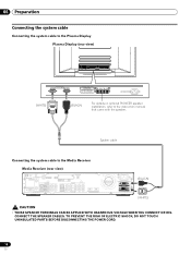
... the sleep timer. • When using the remote control unit, point it into standby mode. 2 Transmission confirmation LED 3 INPUT: Selects an input source of the Plasma Display. (INPUT 1, INPUT 2, INPUT 3, INPUT 4, PC, i.LINK) 4 •(dot): Enters a dot. 5 CH RETURN: Returns to the previous channel. 14... channels by pressing A, B, C and D. 24 SCREEN SIZE: Selects the screen size. 25 DISPLAY: Displays the channel information. 26 AV SELECTION: Selects audio and video settings. (AV mode: STANDARD, DYNAMIC, MOVIE, GAME, USER. 05 Part Names Remote control unit Mode switch (with 1 2 "TV" ...
... the sleep timer. • When using the remote control unit, point it into standby mode. 2 Transmission confirmation LED 3 INPUT: Selects an input source of the Plasma Display. (INPUT 1, INPUT 2, INPUT 3, INPUT 4, PC, i.LINK) 4 •(dot): Enters a dot. 5 CH RETURN: Returns to the previous channel. 14... channels by pressing A, B, C and D. 24 SCREEN SIZE: Selects the screen size. 25 DISPLAY: Displays the channel information. 26 AV SELECTION: Selects audio and video settings. (AV mode: STANDARD, DYNAMIC, MOVIE, GAME, USER. 05 Part Names Remote control unit Mode switch (with 1 2 "TV" ...
Owner's Manual
Page 18
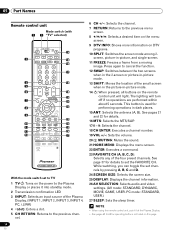
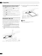
... cable Connecting the system cable to the Plasma Display Plasma Display (rear view) (WHITE) (BLACK) For details on optional PIONEER speaker installation, refer to the Media Receiver Media Receiver (rear view) IN OUT VCR CONTROL CONTROL IN ANTENNA B ANTENNA/ CABLE A IN Cable CARD S-VIDEO INPUT 2 VIDEO R-AUDIO-L DIGITAL OUT OPTICAL (TS) S400 VIDEO INPUT...
... cable Connecting the system cable to the Plasma Display Plasma Display (rear view) (WHITE) (BLACK) For details on optional PIONEER speaker installation, refer to the Media Receiver Media Receiver (rear view) IN OUT VCR CONTROL CONTROL IN ANTENNA B ANTENNA/ CABLE A IN Cable CARD S-VIDEO INPUT 2 VIDEO R-AUDIO-L DIGITAL OUT OPTICAL (TS) S400 VIDEO INPUT...
Owner's Manual
Page 22
... selected will switch the selected screen to a TV image. Tab DIGOIPTTAILCAOLUT CCaAbRleD AUDIO-L (TS) VIDEO S400 INPUT 1 COMPCOBN/PEBNT Y CVIRD/EPOR R-AUDIO-L CR/PR INPUT 1 22 En DIGOIPTTAILCAOLUT ACNATBELNENAAI/N CCaAbRleD N P UVTI 2 DEO R-AUDIO-L VIDEO R-AUDIO-L (TS) VIDEO S400 R-AUDIO-L COMPCOBN/PEBNT CVIRD/EPOR Y S-VIDEO R-AUDIO-L INPUT 3 Y CB/PB CR/PR INPUT 1 H • Be sure to insert...
... selected will switch the selected screen to a TV image. Tab DIGOIPTTAILCAOLUT CCaAbRleD AUDIO-L (TS) VIDEO S400 INPUT 1 COMPCOBN/PEBNT Y CVIRD/EPOR R-AUDIO-L CR/PR INPUT 1 22 En DIGOIPTTAILCAOLUT ACNATBELNENAAI/N CCaAbRleD N P UVTI 2 DEO R-AUDIO-L VIDEO R-AUDIO-L (TS) VIDEO S400 R-AUDIO-L COMPCOBN/PEBNT CVIRD/EPOR Y S-VIDEO R-AUDIO-L INPUT 3 Y CB/PB CR/PR INPUT 1 H • Be sure to insert...
Owner's Manual
Page 23
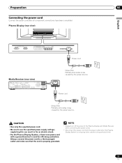
Plasma Display (rear view) English Power cord Media Receiver (rear view) IN OUT CONTROL VCR CONTROL IN ANTENNA B ANTENNA/ CABLE A IN Cable CARD S-VIDEO INPUT 2 INPUT 2 VIDEO R-AUDIO-L DIGITAL OUT OPTICAL (TS) S400 VIDEO INPUT 1 COMPONENT VIDEO R-AUDIO-L Y CB/PB CR/PR SERVICE ONLY OUT MONITOR OUT S-VIDEO VIDEO R-AUDIO-L S-VIDEO R-AUDIO...used for a long period of time. 23 En neglecting this can result in fire or electric shock. • For the Plasma Display System, a three-core power cord with a ground terminal is not going to a three-pronged outlet and make sure ...
Plasma Display (rear view) English Power cord Media Receiver (rear view) IN OUT CONTROL VCR CONTROL IN ANTENNA B ANTENNA/ CABLE A IN Cable CARD S-VIDEO INPUT 2 INPUT 2 VIDEO R-AUDIO-L DIGITAL OUT OPTICAL (TS) S400 VIDEO INPUT 1 COMPONENT VIDEO R-AUDIO-L Y CB/PB CR/PR SERVICE ONLY OUT MONITOR OUT S-VIDEO VIDEO R-AUDIO-L S-VIDEO R-AUDIO...used for a long period of time. 23 En neglecting this can result in fire or electric shock. • For the Plasma Display System, a three-core power cord with a ground terminal is not going to a three-pronged outlet and make sure ...

Owner's Manual
Page 27
...POD display. • If you have selected a digital TV program that provides multilanguage services, you may enjoy stereo sound and/or Secondary Audio Programs (SAP), using the menu, POD information is automatically acquired even when the system is determined by the cable TV company. Each time... mode. Each time you will hear that are received through language setting is available when the channel or program is selected, the Plasma Display System sound remains mono even if the system receives a stereo broadcast. This service presents various types of useful information, using the...
...POD display. • If you have selected a digital TV program that provides multilanguage services, you may enjoy stereo sound and/or Secondary Audio Programs (SAP), using the menu, POD information is automatically acquired even when the system is determined by the cable TV company. Each time... mode. Each time you will hear that are received through language setting is available when the channel or program is selected, the Plasma Display System sound remains mono even if the system receives a stereo broadcast. This service presents various types of useful information, using the...
Owner's Manual
Page 30
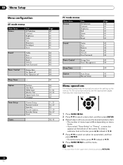
.... 4 Press / to the upper menu levels by pressing RETURN. Option Position Side Mask HDMI Input Monitor Out Digital Audio Out Language Tuner Setup Timers Channel Setup Parental Control Favorites Closed Captions Recorder Setup Clock - 30 En Page 40 41 ...41 41 41 41 41 41 42 42 42 42 43 43 43 43 44 40 44 47 51, 52 52, 53 54 47 31, 32 33-37 37 37-39 56...Timer - Option Auto Setup Manual Setup Page 40 41 41 41 41 41 41 42 42 42 42 43 43 43 44 40 45 45 Menu operations The following describes the typical procedure for setting up the menus. For ...
.... 4 Press / to the upper menu levels by pressing RETURN. Option Position Side Mask HDMI Input Monitor Out Digital Audio Out Language Tuner Setup Timers Channel Setup Parental Control Favorites Closed Captions Recorder Setup Clock - 30 En Page 40 41 ...41 41 41 41 41 41 42 42 42 42 43 43 43 43 44 40 44 47 51, 52 52, 53 54 47 31, 32 33-37 37 37-39 56...Timer - Option Auto Setup Manual Setup Page 40 41 41 41 41 41 41 42 42 42 42 43 43 43 44 40 45 45 Menu operations The following describes the typical procedure for setting up the menus. For ...
Owner's Manual
Page 42
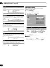
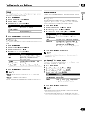
... FOCUS Front Surround 2 0 0 Off Off Item Treble Bass Balance button For weaker treble button For stronger treble For weaker bass For stronger bass Decreases audio from Decreases audio from video images when a digital TV channel is watched or a DVD is played, resulting in noise-free images. Press / to your preference for Digital...
... FOCUS Front Surround 2 0 0 Off Off Item Treble Bass Balance button For weaker treble button For stronger treble For weaker bass For stronger bass Decreases audio from Decreases audio from video images when a digital TV channel is watched or a DVD is played, resulting in noise-free images. Press / to your preference for Digital...
Owner's Manual
Page 43
...ENTER) 3 Select "Front Surround". ( / ) 4 Select the desired parameter. ( / ) Item Description Off Deactivates both TruBass and SRS effects. 5 Press HOME MENU to enjoy only audio, you need not watch the screen and want to exit the menu. • (WOW) designates a status where the FOCUS is on and TruBass + SRS has... Does not place the system into the standby mode when noise signals are present at the Media Receiver after a TV program finishes. 43 En TruBass Provides deep, rich bass using the Home menu when the input source is incorporated under license from SRS Labs, Inc. ...
...ENTER) 3 Select "Front Surround". ( / ) 4 Select the desired parameter. ( / ) Item Description Off Deactivates both TruBass and SRS effects. 5 Press HOME MENU to enjoy only audio, you need not watch the screen and want to exit the menu. • (WOW) designates a status where the FOCUS is on and TruBass + SRS has... Does not place the system into the standby mode when noise signals are present at the Media Receiver after a TV program finishes. 43 En TruBass Provides deep, rich bass using the Home menu when the input source is incorporated under license from SRS Labs, Inc. ...

Owner's Manual
Page 50
... OUT MONITOR OUT S-VIDEO VIDEO R-AUDIO-L S-VIDEO R-AUDIO-L IINNPUTT 33 Y CB/PB CR/PR INPUT 1 INPUT HDMI AV cable (commercially available) S-Video cable (commercially available) DVD player VCR Displaying a VCR image To watch a DVD image, press INPUT 1 on the remote control unit or press INPUT on the Plasma Display to select INPUT2. •...
... OUT MONITOR OUT S-VIDEO VIDEO R-AUDIO-L S-VIDEO R-AUDIO-L IINNPUTT 33 Y CB/PB CR/PR INPUT 1 INPUT HDMI AV cable (commercially available) S-Video cable (commercially available) DVD player VCR Displaying a VCR image To watch a DVD image, press INPUT 1 on the remote control unit or press INPUT on the Plasma Display to select INPUT2. •...

Owner's Manual
Page 51
... INPUT 3 terminals include HDMI terminals to be received from the connected equipment. To use the HDMI terminal, activate the terminal and specify the types of audio signals. ( / then ENTER) • If you select "Auto", an attempt will be made to select INPUT 1 (or INPUT 3). Input signal correlation table ...video signals are not supported. Before starting the menu, press INPUT 1 (or INPUT 3) on the remote control unit or press INPUT on the Plasma Display to identify the type of digital video signals. ( / then ENTER) • If you select "Auto", an attempt will be input.
... INPUT 3 terminals include HDMI terminals to be received from the connected equipment. To use the HDMI terminal, activate the terminal and specify the types of audio signals. ( / then ENTER) • If you select "Auto", an attempt will be made to select INPUT 1 (or INPUT 3). Input signal correlation table ...video signals are not supported. Before starting the menu, press INPUT 1 (or INPUT 3) on the remote control unit or press INPUT on the Plasma Display to identify the type of digital video signals. ( / then ENTER) • If you select "Auto", an attempt will be input.

Owner's Manual
Page 52
...by using the recording equipment. Media Receiver (front view) COMPONENT VIDEO Y CB / PB CR / PR INPUT 4 S-VIDEO VIDEO AUDIO L R AUDIO (STEREO) PC ANALOG RGB AV cable (commercially available) S-Video cable (commercially available) • The INPUT 4 terminals are to ...; Connect external equipment to only terminals that came with the connected equipment. • Depending on the Plasma Display to be actually used. Digital Accepts digital audio signals. Component Video cable (commercially available) Game console/Camcorder 52 En Displaying an image of images. ...
...by using the recording equipment. Media Receiver (front view) COMPONENT VIDEO Y CB / PB CR / PR INPUT 4 S-VIDEO VIDEO AUDIO L R AUDIO (STEREO) PC ANALOG RGB AV cable (commercially available) S-Video cable (commercially available) • The INPUT 4 terminals are to ...; Connect external equipment to only terminals that came with the connected equipment. • Depending on the Plasma Display to be actually used. Digital Accepts digital audio signals. Component Video cable (commercially available) Game console/Camcorder 52 En Displaying an image of images. ...

Owner's Manual
Page 53
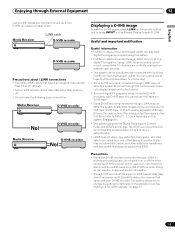
... to the MONITOR OUT terminals, select an input source (e.g., TV channel reception) on the recording equipment other audio equipment The digital audio output terminal (optical) on this system can output Dolby Digital signals. For more information, see the instruction ... AV cable (commercially available) S-Video cable (commercially available) Connecting other than external input sources. Optical digital cable (commercially available) Audio cable (commercially available) AV receiver 53 En Connecting an AV receiver Media Receiver (rear view) VCR controller (for presetting digital TV...
... to the MONITOR OUT terminals, select an input source (e.g., TV channel reception) on the recording equipment other audio equipment The digital audio output terminal (optical) on this system can output Dolby Digital signals. For more information, see the instruction ... AV cable (commercially available) S-Video cable (commercially available) Connecting other than external input sources. Optical digital cable (commercially available) Audio cable (commercially available) AV receiver 53 En Connecting an AV receiver Media Receiver (rear view) VCR controller (for presetting digital TV...
Owner's Manual
Page 54
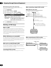
...this system supports only D-VHS recorders. With D-VHS recorders connected to this PDP system to control one of the Media Receiver. Watching a D-VHS image What is Sony's term for the DIGITAL AUDIO output terminal (OPTICAL), depending on the rear of up for the IEEE ... two D-VHS recorders directly to the i.LINK terminals on your AV receiver. 1 Press HOME MENU. 2 Select "Option". ( / then ENTER) 3 Select "Digital Audio Out". ( / then ENTER) 4 Select "Dolby Digital" or "PCM". ( / then ENTER) Item Description PCM Always outputs in two directions. Connecting D-VHS recorders...
...this system supports only D-VHS recorders. With D-VHS recorders connected to this PDP system to control one of the Media Receiver. Watching a D-VHS image What is Sony's term for the DIGITAL AUDIO output terminal (OPTICAL), depending on the rear of up for the IEEE ... two D-VHS recorders directly to the i.LINK terminals on your AV receiver. 1 Press HOME MENU. 2 Select "Option". ( / then ENTER) 3 Select "Digital Audio Out". ( / then ENTER) 4 Select "Dolby Digital" or "PCM". ( / then ENTER) Item Description PCM Always outputs in two directions. Connecting D-VHS recorders...
Owner's Manual
Page 55
...LINK cables that presents data coding and device authentication. • i.LINK may not allow video, audio, and other connected D-VHS recorder (not in the standby mode. You can also connect up to... watch a D-VHS image, press i.LINK on the remote control unit or press INPUT on the Plasma Display to select i.LINK. If this system. • D-VHS recorders connected through i.LINK can record...Some D-VHS recorders connected though i.LINK may not allow this system to control through the control panel screen or to display images and output sound. • To record digital TV programs using ...
...LINK cables that presents data coding and device authentication. • i.LINK may not allow video, audio, and other connected D-VHS recorder (not in the standby mode. You can also connect up to... watch a D-VHS image, press i.LINK on the remote control unit or press INPUT on the Plasma Display to select i.LINK. If this system. • D-VHS recorders connected through i.LINK can record...Some D-VHS recorders connected though i.LINK may not allow this system to control through the control panel screen or to display images and output sound. • To record digital TV programs using ...

Owner's Manual
Page 58
Media Receiver (front view) EC DATA ER ACQUISITION COMPONENT VIDEO Y CB / PB CR / PR INPUT 4 S-VIDEO VIDEO AUDIO L R AUDIO (STEREO) PC ANALOG RGB ø 3.5 mm stereo miniplug cable (commercially available) RGB cable (commercially available) Signal names for 15-pin mini D-sub connecter Pin No. 1 2 3 4 5 6 7 8...PC terminals to connect a personal computer. • The PC input terminals are DDC2B-compatible. • Plug & Play may not correctly function, depending on the Plasma Display to select "PC". • The PC terminals cannot be required for audiovisual equipment.
Media Receiver (front view) EC DATA ER ACQUISITION COMPONENT VIDEO Y CB / PB CR / PR INPUT 4 S-VIDEO VIDEO AUDIO L R AUDIO (STEREO) PC ANALOG RGB ø 3.5 mm stereo miniplug cable (commercially available) RGB cable (commercially available) Signal names for 15-pin mini D-sub connecter Pin No. 1 2 3 4 5 6 7 8...PC terminals to connect a personal computer. • The PC input terminals are DDC2B-compatible. • Plug & Play may not correctly function, depending on the Plasma Display to select "PC". • The PC terminals cannot be required for audiovisual equipment.
Owner's Manual
Page 59
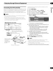
...IN ANTENNA B ANTENNA/ CABLE A IN Cable CARD S-VIDEO INPUT 2 VIDEO R-AUDIO-L DIGITAL O OPTICA (TS) S400 VIDEO INPUT 1 COMPON R-AUDIO-L Y CB/ SERVICE ONLY OUT MONITOR OUT S-VIDEO VIDEO R-AUDIO-L S-VIDEO R-AUDIO-L IINNPUTT 33 Y CB/ (Once you to the CONTROL IN or CONTROL OUT ...VCR controller Connect the supplied VCR controller to the recording equipment is not recording. • The recording test takes approximately 10 seconds. • The PIONEER 1 (DVD recorder) has been set the manufacture of the recording equipment: 1 Press HOME MENU. 2 Select "Tuner Setup". ( / then ENTER...
...IN ANTENNA B ANTENNA/ CABLE A IN Cable CARD S-VIDEO INPUT 2 VIDEO R-AUDIO-L DIGITAL O OPTICA (TS) S400 VIDEO INPUT 1 COMPON R-AUDIO-L Y CB/ SERVICE ONLY OUT MONITOR OUT S-VIDEO VIDEO R-AUDIO-L S-VIDEO R-AUDIO-L IINNPUTT 33 Y CB/ (Once you to the CONTROL IN or CONTROL OUT ...VCR controller Connect the supplied VCR controller to the recording equipment is not recording. • The recording test takes approximately 10 seconds. • The PIONEER 1 (DVD recorder) has been set the manufacture of the recording equipment: 1 Press HOME MENU. 2 Select "Tuner Setup". ( / then ENTER...


