Owner's Manual
Page 3
... are designed to correct the interference by turning the equipment off and on, the user is located on the rear panel. BOX 1760, LONG BEACH, CA., 90801-1760 U.S.A. WARNING: Handling the cord on this serial number on a circuit...WARNING: Be sure to other reproductive harm. Product Name: Plasma Display System (Plasma Display) (Media Receiver) Model Number: PDP-5045HD PDP-4345HD (PDP-504PU) (PDP-434PU) (PDP-R05U) (PDP-R05U) Product Category: Class B Personal Computers & Peripherals Responsible Party Name: PIONEER ELECTRONICS (USA), INC., Customer Support Div. Please write...
... are designed to correct the interference by turning the equipment off and on, the user is located on the rear panel. BOX 1760, LONG BEACH, CA., 90801-1760 U.S.A. WARNING: Handling the cord on this serial number on a circuit...WARNING: Be sure to other reproductive harm. Product Name: Plasma Display System (Plasma Display) (Media Receiver) Model Number: PDP-5045HD PDP-4345HD (PDP-504PU) (PDP-434PU) (PDP-R05U) (PDP-R05U) Product Category: Class B Personal Computers & Peripherals Responsible Party Name: PIONEER ELECTRONICS (USA), INC., Customer Support Div. Please write...
Owner's Manual
Page 4
... Guidance Information 02 Safety Precautions 03 Operational Precautions 04 Supplied Accessories Plasma Display 11 Media Receiver 11 05 Part Names Plasma Display 12 Media Receiver 12 Remote control unit 14 06 Preparation Installing the Plasma Display 15 Installing the Media Receiver 16 Installing the Media Receiver ...Selecting the type of the power plug and power outlet may sometimes differ from that shown in a safe place for buying this Pioneer product. Please read through these operating instructions so you for future reference. Contents Thank you will know how to operate your ...
... Guidance Information 02 Safety Precautions 03 Operational Precautions 04 Supplied Accessories Plasma Display 11 Media Receiver 11 05 Part Names Plasma Display 12 Media Receiver 12 Remote control unit 14 06 Preparation Installing the Plasma Display 15 Installing the Media Receiver 16 Installing the Media Receiver ...Selecting the type of the power plug and power outlet may sometimes differ from that shown in a safe place for buying this Pioneer product. Please read through these operating instructions so you for future reference. Contents Thank you will know how to operate your ...
Owner's Manual
Page 6
... residual images upon the phosphors of the panel and the existence of a minute number of inactive light cells in the screen are not covered by local warranties. 6 En By following the recommendations listed below . PIONEER will not be assured of a phosphor-based...order to cool the internal electronics and prevent a hazardous occurrence. Over the course of its lifetime, the luminosity of the Pioneer PDP-5045HD/PDP-4345HD Plasma Display System will automatically power off in possible malfunction. Usage guidelines All phosphor-based screens (including conventional tube-type televisions)...
... residual images upon the phosphors of the panel and the existence of a minute number of inactive light cells in the screen are not covered by local warranties. 6 En By following the recommendations listed below . PIONEER will not be assured of a phosphor-based...order to cool the internal electronics and prevent a hazardous occurrence. Over the course of its lifetime, the luminosity of the Pioneer PDP-5045HD/PDP-4345HD Plasma Display System will automatically power off in possible malfunction. Usage guidelines All phosphor-based screens (including conventional tube-type televisions)...

Owner's Manual
Page 7
...lag image) due to burning Avoid displaying the same image on the Plasma Display continuously over several days, a permanent after-image may cause ... can be set to help prevent damage from screen burning (see page 43). USE ONLY WITH A CART, STAND, TRIPOD, BRACKET, OR TABLE ...luminance are displayed. If the same image is operated through i.LINK PIONEER shall not always assure normal video/audio recording or playback when a...ACCESSORIES RECOMMENDED BY THE MANUFACTURER. Important User Guidance Information 01 English Panel sticking and after-image lag • Displaying the same images such...
...lag image) due to burning Avoid displaying the same image on the Plasma Display continuously over several days, a permanent after-image may cause ... can be set to help prevent damage from screen burning (see page 43). USE ONLY WITH A CART, STAND, TRIPOD, BRACKET, OR TABLE ...luminance are displayed. If the same image is operated through i.LINK PIONEER shall not always assure normal video/audio recording or playback when a...ACCESSORIES RECOMMENDED BY THE MANUFACTURER. Important User Guidance Information 01 English Panel sticking and after-image lag • Displaying the same images such...
Owner's Manual
Page 8
... shock and/or short internal parts. Request a qualified service person to service the product yourself. Repair-If any of the front protection panel changes, resulting in your home, consult your product, please read and understood before cleaning the product. When the product has been exposed ... checks-Upon completion of the product. The screen may be followed. 5. The Plasma Display weighs about 38 kg (83.8 lbs.) for the PDP-504PU and about 30.5 kg (67.3 lbs.) for built-in case the plasma Display breaks. 14. 02 Safety Precautions Electricity is operated. 2. Attachments-Do not...
... shock and/or short internal parts. Request a qualified service person to service the product yourself. Repair-If any of the front protection panel changes, resulting in your home, consult your product, please read and understood before cleaning the product. When the product has been exposed ... checks-Upon completion of the product. The screen may be followed. 5. The Plasma Display weighs about 38 kg (83.8 lbs.) for the PDP-504PU and about 30.5 kg (67.3 lbs.) for built-in case the plasma Display breaks. 14. 02 Safety Precautions Electricity is operated. 2. Attachments-Do not...
Owner's Manual
Page 9
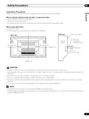
When using other than the optional PIONEER products. 9 En Never use them for mounting non-specified products. • Do not mount or remove the Plasma Display to or from the stand, with speakers attached. • It is strongly recommended to use the supplied bolts. • For .... • Be sure to install the Plasma Display on a flat surface because it contains glass. • The screw holes other items • Consult your dealer to perform the installation. • Be sure to use the optional PIONEER mounting products. • PIONEER shall not be liable for any personal injury...
When using other than the optional PIONEER products. 9 En Never use them for mounting non-specified products. • Do not mount or remove the Plasma Display to or from the stand, with speakers attached. • It is strongly recommended to use the supplied bolts. • For .... • Be sure to install the Plasma Display on a flat surface because it contains glass. • The screw holes other items • Consult your dealer to perform the installation. • Be sure to use the optional PIONEER mounting products. • PIONEER shall not be liable for any personal injury...

Owner's Manual
Page 10
...or coating removal. • If you clean the surface of the cabinet with condensation may make the product contact with a soft dry cloth; Plasma Display protection function When still images (such as shown. • Do not use the handles to protect the screen when detecting still images; ...photos and computer images) stay on the screen for an extended period of time, the screen will be adversely affected. 03 Operational Precautions PIONEER bears no responsibility for any damages arising from incorrect use of the product by you or other people, malfunctions when in use, other ...
...or coating removal. • If you clean the surface of the cabinet with condensation may make the product contact with a soft dry cloth; Plasma Display protection function When still images (such as shown. • Do not use the handles to protect the screen when detecting still images; ...photos and computer images) stay on the screen for an extended period of time, the screen will be adversely affected. 03 Operational Precautions PIONEER bears no responsibility for any damages arising from incorrect use of the product by you or other people, malfunctions when in use, other ...

Owner's Manual
Page 11
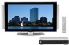
...band × 3 Media Receiver Cleaning cloth Speed clamp × 3 Warranty card Speaker cushion × 3 (Use when installing the optional speakers at the bottom of the Plasma Display.) Power cord (2 m/6.6 feet) Remote control unit System cable (3 m/9.8 feet) AA size battery × 2 (Alkaline battery) Stand Screw × 4 (for ...stand) Screw hole cap × 4 VCR controller (1.8 m/5.9 feet) Operating Instructions Instruction guide • Always use the power cord supplied with the Plasma Display and the one supplied with the Media Receiver for each respective unit. 11 En
...band × 3 Media Receiver Cleaning cloth Speed clamp × 3 Warranty card Speaker cushion × 3 (Use when installing the optional speakers at the bottom of the Plasma Display.) Power cord (2 m/6.6 feet) Remote control unit System cable (3 m/9.8 feet) AA size battery × 2 (Alkaline battery) Stand Screw × 4 (for ...stand) Screw hole cap × 4 VCR controller (1.8 m/5.9 feet) Operating Instructions Instruction guide • Always use the power cord supplied with the Plasma Display and the one supplied with the Media Receiver for each respective unit. 11 En

Owner's Manual
Page 12
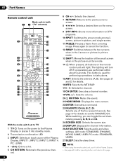
..., CR/PR) 7 INPUT 4 terminal (S-VIDEO) 8 INPUT 4 terminal (VIDEO) 9 INPUT 4 terminals (AUDIO) 10 PC INPUT terminal (AUDIO) 11 PC INPUT terminal (ANALOG RGB) 05 Part Names Plasma Display Front view Rear view (right view) 5 6 7 8 4 1 POWER button 2 STANDBY indicator 3 POWER ON indicator 4 Remote control sensor 5 STANDBY/ON button 6 INPUT button 7 VOLUME +/- buttons 8 CHANNEL...
..., CR/PR) 7 INPUT 4 terminal (S-VIDEO) 8 INPUT 4 terminal (VIDEO) 9 INPUT 4 terminals (AUDIO) 10 PC INPUT terminal (AUDIO) 11 PC INPUT terminal (ANALOG RGB) 05 Part Names Plasma Display Front view Rear view (right view) 5 6 7 8 4 1 POWER button 2 STANDBY indicator 3 POWER ON indicator 4 Remote control sensor 5 STANDBY/ON button 6 INPUT button 7 VOLUME +/- buttons 8 CHANNEL...
Owner's Manual
Page 14
... 24 11 25 12 26 13 27 With the mode switch set to TV 1 TV : Turns on the power to the Plasma Display or places it at the Plasma Display. • See pages 62 to 68 for operating buttons not listed on DTV programs. 10 SPLIT: Switches the screen mode... the sleep timer. • When using the remote control unit, point it into standby mode. 2 Transmission confirmation LED 3 INPUT: Selects an input source of the Plasma Display. (INPUT 1, INPUT 2, INPUT 3, INPUT 4, PC, i.LINK) 4 •(dot): Enters a dot. 5 CH RETURN: Returns to the previous channel. 14 En 6 CH +/-: Selects the channel. ...
... 24 11 25 12 26 13 27 With the mode switch set to TV 1 TV : Turns on the power to the Plasma Display or places it at the Plasma Display. • See pages 62 to 68 for operating buttons not listed on DTV programs. 10 SPLIT: Switches the screen mode... the sleep timer. • When using the remote control unit, point it into standby mode. 2 Transmission confirmation LED 3 INPUT: Selects an input source of the Plasma Display. (INPUT 1, INPUT 2, INPUT 3, INPUT 4, PC, i.LINK) 4 •(dot): Enters a dot. 5 CH RETURN: Returns to the previous channel. 14 En 6 CH +/-: Selects the channel. ...
Owner's Manual
Page 15
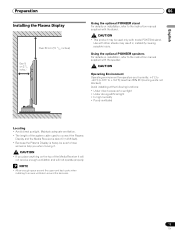
... direct sunlight. Maintain adequate ventilation. • The length of the system cable used to connect the Plasma Display and the Media Receiver is about 3 m (9.8 feet). • Because the Plasma Display is heavy, be used only with other stands may be sure to have someone help you when... the following locations: • Under direct exposure to +104°F); Preparation Installing the Plasma Display Over 50 cm (19 /11 16 inches) Over 10 cm (3 15/ 16 inches ) 06 Using the optional PIONEER stand For details on installation, refer to the instruction manual supplied with the stand. &#...
... direct sunlight. Maintain adequate ventilation. • The length of the system cable used to connect the Plasma Display and the Media Receiver is about 3 m (9.8 feet). • Because the Plasma Display is heavy, be used only with other stands may be sure to have someone help you when... the following locations: • Under direct exposure to +104°F); Preparation Installing the Plasma Display Over 50 cm (19 /11 16 inches) Over 10 cm (3 15/ 16 inches ) 06 Using the optional PIONEER stand For details on installation, refer to the instruction manual supplied with the stand. &#...

Owner's Manual
Page 16
... Receiver. • Do not block the side cooling vents or the rear ventilation fan opening of the Media Receiver. 06 Preparation Installing the Media Receiver Plasma Display Media Receiver (vertical installation) ACQUISITION TIMER STANDBY ON DATA REC POWER Installing the Media Receiver vertically You can use the supplied stand to install...
... Receiver. • Do not block the side cooling vents or the rear ventilation fan opening of the Media Receiver. 06 Preparation Installing the Media Receiver Plasma Display Media Receiver (vertical installation) ACQUISITION TIMER STANDBY ON DATA REC POWER Installing the Media Receiver vertically You can use the supplied stand to install...
Owner's Manual
Page 18
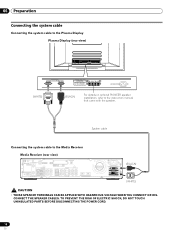
06 Preparation Connecting the system cable Connecting the system cable to the Plasma Display Plasma Display (rear view) (WHITE) (BLACK) For details on optional PIONEER speaker installation, refer to the Media Receiver Media Receiver (rear view) IN OUT VCR CONTROL CONTROL IN ANTENNA B ANTENNA/ CABLE A IN Cable CARD S-VIDEO INPUT 2 ...
06 Preparation Connecting the system cable Connecting the system cable to the Plasma Display Plasma Display (rear view) (WHITE) (BLACK) For details on optional PIONEER speaker installation, refer to the Media Receiver Media Receiver (rear view) IN OUT VCR CONTROL CONTROL IN ANTENNA B ANTENNA/ CABLE A IN Cable CARD S-VIDEO INPUT 2 ...
Owner's Manual
Page 19
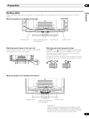
... Attach the speed clamps using the 4 holes marked with below to undo once in place. When the speakers are installed on the rear of the Plasma Display and snap [2] into the back of the cables. 19 En
... Attach the speed clamps using the 4 holes marked with below to undo once in place. When the speakers are installed on the rear of the Plasma Display and snap [2] into the back of the cables. 19 En

Owner's Manual
Page 20
When you place such equipment operated through infrared remote control as a VCR nearby, that equipment at the bottom right of the front panel of the Plasma Display. In such case, change the angle of new batteries or cause chemical leakage in old batteries. • Do not leave dead ... in the remote control unit; Mixing old and new batteries can function within 30 degrees in the unit are empty. The strength of the Plasma Display is under direct sunlight; If you will occur. Cautions regarding batteries • The remote control unit cannot operate the system if the ...
When you place such equipment operated through infrared remote control as a VCR nearby, that equipment at the bottom right of the front panel of the Plasma Display. In such case, change the angle of new batteries or cause chemical leakage in old batteries. • Do not leave dead ... in the remote control unit; Mixing old and new batteries can function within 30 degrees in the unit are empty. The strength of the Plasma Display is under direct sunlight; If you will occur. Cautions regarding batteries • The remote control unit cannot operate the system if the ...
Owner's Manual
Page 23
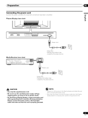
...power cord Connect the power cord after all component connections have been completed. neglecting this can result in fire or electric shock. • For the Plasma Display System, a three-core power cord with a ground terminal is not going to be used for a long period of time. 23 En Always... connect the power cord to use the specified power supply voltage; Plasma Display (rear view) English Power cord Media Receiver (rear view) IN OUT CONTROL VCR CONTROL IN ANTENNA B ANTENNA/ CABLE A IN Cable CARD S-VIDEO ...
...power cord Connect the power cord after all component connections have been completed. neglecting this can result in fire or electric shock. • For the Plasma Display System, a three-core power cord with a ground terminal is not going to be used for a long period of time. 23 En Always... connect the power cord to use the specified power supply voltage; Plasma Display (rear view) English Power cord Media Receiver (rear view) IN OUT CONTROL VCR CONTROL IN ANTENNA B ANTENNA/ CABLE A IN Cable CARD S-VIDEO ...
Owner's Manual
Page 24
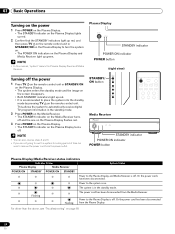
..." on . The system is off . Or the power cord has been disconnected from the power outlet. Plasma Display STANDBY indicator POWER ON indicator POWER button • In this manual, "system" means the Plasma Display Panel and Media Receiver. (right view) Turning off . • You can also reverse steps 2 and 3.... • If you are not going to use this system for a long period of time, be sure to the Plasma Display and Media Receiver is in ...
..." on . The system is off . Or the power cord has been disconnected from the power outlet. Plasma Display STANDBY indicator POWER ON indicator POWER button • In this manual, "system" means the Plasma Display Panel and Media Receiver. (right view) Turning off . • You can also reverse steps 2 and 3.... • If you are not going to use this system for a long period of time, be sure to the Plasma Display and Media Receiver is in ...

Owner's Manual
Page 25
... control unit Select channels directly by TV stations as CH +/- Changing channels To increase the channel number, press CH + on the Plasma Display operates the same as necessary when in the channel more information about the currently selected channel. Press CH RETURN again to 9. ...To clear the channel banner, press DTV INFO. Plasma Display (right view) CHANNEL +/- To decrease the channel number, press CH -. • CHANNEL +/- on the remote control unit. For more quickly...
... control unit Select channels directly by TV stations as CH +/- Changing channels To increase the channel number, press CH + on the Plasma Display operates the same as necessary when in the channel more information about the currently selected channel. Press CH RETURN again to 9. ...To clear the channel banner, press DTV INFO. Plasma Display (right view) CHANNEL +/- To decrease the channel number, press CH -. • CHANNEL +/- on the remote control unit. For more quickly...

Owner's Manual
Page 26
..., press VOL -. • VOLUME +/- To quit muting, press MUTING again. Pressing DTV INFO again causes the banner to restore the previous program description. 26 En Plasma Display (right view) VOLUME +/- A or Ant. Press to disappear. Volume adjustment Muting 1 234 12:33pm WXCD • 1000 Ant. B) 5 Program time schedule 6 Program title 7 TV...:30pm - 2:00pm 5 6 7 1 Station name 2 Current time 3 Channel number 4 Input (Ant. on the remote control unit. • To mute the sound output, press MUTING. on the Plasma Display operates the same as VOL +/-
..., press VOL -. • VOLUME +/- To quit muting, press MUTING again. Pressing DTV INFO again causes the banner to restore the previous program description. 26 En Plasma Display (right view) VOLUME +/- A or Ant. Press to disappear. Volume adjustment Muting 1 234 12:33pm WXCD • 1000 Ant. B) 5 Program time schedule 6 Program title 7 TV...:30pm - 2:00pm 5 6 7 1 Station name 2 Current time 3 Channel number 4 Input (Ant. on the remote control unit. • To mute the sound output, press MUTING. on the Plasma Display operates the same as VOL +/-

Owner's Manual
Page 27
... can use the POD service provided by the video source. SAP sound: Listen to second language, supplementary commentary and other information. (SAP is selected, the Plasma Display System sound remains mono even if the system receives a stereo broadcast. See page 32. Setting MTS/SAP mode When watching conventional TV programs, you...
... can use the POD service provided by the video source. SAP sound: Listen to second language, supplementary commentary and other information. (SAP is selected, the Plasma Display System sound remains mono even if the system receives a stereo broadcast. See page 32. Setting MTS/SAP mode When watching conventional TV programs, you...


