
Owner's Manual
Page 2
I 4 Fold out this page Contents Removing the carrying case cover Foot control receptacle Electrical connection Foot control Disengaging motor Removing bobbin case and bobbin Disengaging the sewing mechanism Bobbin ...winding Inserting the bobbin Inserting the bobbin case Upper threading Threadingtheneedle Drawing up the bobbin thread Presser bar lifter Thread cutter Regulating the stitch length Sewing straight stitches Zigzag stitches Needle position Selecting utility stitches, 802 to 807...
I 4 Fold out this page Contents Removing the carrying case cover Foot control receptacle Electrical connection Foot control Disengaging motor Removing bobbin case and bobbin Disengaging the sewing mechanism Bobbin ...winding Inserting the bobbin Inserting the bobbin case Upper threading Threadingtheneedle Drawing up the bobbin thread Presser bar lifter Thread cutter Regulating the stitch length Sewing straight stitches Zigzag stitches Needle position Selecting utility stitches, 802 to 807...
Owner's Manual
Page 4
...coloured markings identifying the terminals in the sewing lamp. b) Make sure you unplug the lead whenever you have to change the needle, sewing foot, bobbin or needle plate, or when you clean or oil the machine or have to fitted. The wires in this mains lead are ... selector dial (802-807) 6 Buttonhole and needle positioning lever 7 Spool pins 8 Bobbin winder 9 Hand wheel 10 Stop motion knob 11 Stitch length control 12 Reverse feed control 13 Base (on portable machines) 14 Needle plate 15 Bed cover 16 Sewing foot holder with sewing foot 17 Sewing foot retaining screw 18 Presser...
...coloured markings identifying the terminals in the sewing lamp. b) Make sure you unplug the lead whenever you have to change the needle, sewing foot, bobbin or needle plate, or when you clean or oil the machine or have to fitted. The wires in this mains lead are ... selector dial (802-807) 6 Buttonhole and needle positioning lever 7 Spool pins 8 Bobbin winder 9 Hand wheel 10 Stop motion knob 11 Stitch length control 12 Reverse feed control 13 Base (on portable machines) 14 Needle plate 15 Bed cover 16 Sewing foot holder with sewing foot 17 Sewing foot retaining screw 18 Presser...
Owner's Manual
Page 5
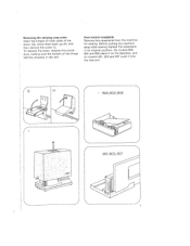
On models 800, 802 and 806 place it into the free arm. 7 -/ 800,802,806 4/- Foot control receptacle Remove this proce dure, making sure the bottom of the cover (G), move them back up (H) and then remove the cover (I). J 1 Before putting the machine away after sewing replace the receptacle in the slot. To replace the cover, reverse this receptacle from the machine for sewing. Removing the carrying case cover Open the hinges on models 801, 803 and 807 push it on the bed plate, and on both sides of the hinge catches properly in its original position.
On models 800, 802 and 806 place it into the free arm. 7 -/ 800,802,806 4/- Foot control receptacle Remove this proce dure, making sure the bottom of the cover (G), move them back up (H) and then remove the cover (I). J 1 Before putting the machine away after sewing replace the receptacle in the slot. To replace the cover, reverse this receptacle from the machine for sewing. Removing the carrying case cover Open the hinges on models 801, 803 and 807 push it on the bed plate, and on both sides of the hinge catches properly in its original position.
Owner's Manual
Page 20
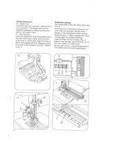
...arrow L moves along the right or left zipper chain. Special sewing feet G Zipper foot Insert the rear pin in groove I, and the front pin in the buttonhole sector of stitch length control 11. H = Darning foot Raise the needle bar. Push bracket M toward the back and hold it in hole ...zipper foot can be adjusted sideways for straight stitching. Release bracket M so that it bears against its stop. lever Insert the filler cord as follows (Fig. This determines the buttonhole length. 16 Set the stitch and density in groove J. Buttonhole settings On models 5 to B. 802 to 807 ...
...arrow L moves along the right or left zipper chain. Special sewing feet G Zipper foot Insert the rear pin in groove I, and the front pin in the buttonhole sector of stitch length control 11. H = Darning foot Raise the needle bar. Push bracket M toward the back and hold it in hole ...zipper foot can be adjusted sideways for straight stitching. Release bracket M so that it bears against its stop. lever Insert the filler cord as follows (Fig. This determines the buttonhole length. 16 Set the stitch and density in groove J. Buttonhole settings On models 5 to B. 802 to 807 ...
Owner's Manual
Page 22
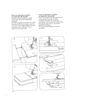
Turn the receptacle round and fit it against the bedplate. Turn catch G on models 601, 803 and 807 Push the workplate over the free arm until it snaps into place. Swing the support down a little after fitting. (Figs. G and H below left.) Fitting the ... back downwards until its two haoks enter the two holes in the machine base. Fitting the detachable workplate on models 800, 802 and 806 The foot control receptacle of these models also serves as a detachable workplate. I) and press it to the machine so that its two guide pins enter the holes provided...
Turn the receptacle round and fit it against the bedplate. Turn catch G on models 601, 803 and 807 Push the workplate over the free arm until it snaps into place. Swing the support down a little after fitting. (Figs. G and H below left.) Fitting the ... back downwards until its two haoks enter the two holes in the machine base. Fitting the detachable workplate on models 800, 802 and 806 The foot control receptacle of these models also serves as a detachable workplate. I) and press it to the machine so that its two guide pins enter the holes provided...


