

WVCU360C User Guide
Page 2
... important operating and maintenance (servicing) instructions in a commercial environment. Any changes or modifications not expressly approved by the party responsible for a Class A digital device, pursuant to Part 15 of the FCC Rules. Serial No. REFER SERVICING TO QUALIFIED SERVICE PERSONNEL. FCC Caution: To assure continued compliance, (example use only shielded interface cables when connecting to persons. You should note the serial number of this unit...
... important operating and maintenance (servicing) instructions in a commercial environment. Any changes or modifications not expressly approved by the party responsible for a Class A digital device, pursuant to Part 15 of the FCC Rules. Serial No. REFER SERVICING TO QUALIFIED SERVICE PERSONNEL. FCC Caution: To assure continued compliance, (example use only shielded interface cables when connecting to persons. You should note the serial number of this unit...

WVCU360C User Guide
Page 4
... 25 s Camera Control 26 s Data Multiplex Unit Control 28 s Video Multiplexer Control 29 s Digital Disk Recorder Control 31 s Alarm Operation 34 REMOTE SETUP of UNITS & CAMERAS 35 s System Unit Setup 35 s Camera Setup 35 s Camera Patrol Learning 36 s Camera Preset Position 37 s VTR (VCR) Control 50 s Camera Setup 51 Chapter 3 For WJ-SX350 Matrix Switcher System 53 MAJOR OPERATING CONTROLS & THEIR FUNCTIONS .... 54 s Front View (Template for WJ-SX350 54 INSTALLATIONS (For WJ-SX350 57 s System Connections 57 s DIP Switch Setting (For WJ-SX350 58 s Controller Number Setting 59...
... 25 s Camera Control 26 s Data Multiplex Unit Control 28 s Video Multiplexer Control 29 s Digital Disk Recorder Control 31 s Alarm Operation 34 REMOTE SETUP of UNITS & CAMERAS 35 s System Unit Setup 35 s Camera Setup 35 s Camera Patrol Learning 36 s Camera Preset Position 37 s VTR (VCR) Control 50 s Camera Setup 51 Chapter 3 For WJ-SX350 Matrix Switcher System 53 MAJOR OPERATING CONTROLS & THEIR FUNCTIONS .... 54 s Front View (Template for WJ-SX350 54 INSTALLATIONS (For WJ-SX350 57 s System Connections 57 s DIP Switch Setting (For WJ-SX350 58 s Controller Number Setting 59...
WVCU360C User Guide
Page 5
...; Camera channel selection • Monitor Selection • Alarm (Display/Suspend/Recall/Reset) • Camera and system unit setup Camera controls • Lens functions: Iris/Focus/Auto Focus/Zoom • Housing: Defroster/Wiper/Auxiliary 1, 2 • Pan/Tilt: Slow Pan/Slow Tilt/Auto Pan/Auto Sort/Auto Sequence/Random Pan/Preset/Home/Camera Patrol In a PS •Data or a WJ-FS616 system • Switching of Live pictures and Playback/Changing the Multiscreen Picture layout...
...; Camera channel selection • Monitor Selection • Alarm (Display/Suspend/Recall/Reset) • Camera and system unit setup Camera controls • Lens functions: Iris/Focus/Auto Focus/Zoom • Housing: Defroster/Wiper/Auxiliary 1, 2 • Pan/Tilt: Slow Pan/Slow Tilt/Auto Pan/Auto Sort/Auto Sequence/Random Pan/Preset/Home/Camera Patrol In a PS •Data or a WJ-FS616 system • Switching of Live pictures and Playback/Changing the Multiscreen Picture layout...

WVCU360C User Guide
Page 6
e Data Ports (DATA) These ports are used to identify it when finished. t Clamp The clamp fastens the power cord to exchange control data with the connected system units via the supplied RS-485 cable. The new settings will take effect when the power is used to the AC adapter. A system may comprise up to a System Controller. w Mode Selection Switches (MODE) The DIP switches are used to assign a controller number to the System Controller to set communication parameters for the DC plug of the supplied AC...
e Data Ports (DATA) These ports are used to identify it when finished. t Clamp The clamp fastens the power cord to exchange control data with the connected system units via the supplied RS-485 cable. The new settings will take effect when the power is used to the AC adapter. A system may comprise up to a System Controller. w Mode Selection Switches (MODE) The DIP switches are used to assign a controller number to the System Controller to set communication parameters for the DC plug of the supplied AC...

WVCU360C User Guide
Page 7
... LOGOUT SET PROGRAM PRESET 1. OPERATE LOCK ALARM UNIT CAMERA ALT MULTI SCREEN SPOT ALM RESET SEQUENCE VTR CAM ALL RESET ALM SUSPEND EL-ZOOM MULTI SELECT FUNCTION PRE-POSI STILL CAMERA SET ON OFF T/L MODE SETUP ON/OFF UNIT ESC CAM SET 360 System Controller WV-CU C For Multiplexer CAMERA SITE CONTROL IRIS CLOSE OPEN IRIS RESET UP AUTO/+ FOCUS NEAR FAR AUX 2 L R HOME/TELE AUX 1 ZOOM WIDE DOWN AUTO FOCUS OPERATE LOGIN ALARM MONITOR...
... LOGOUT SET PROGRAM PRESET 1. OPERATE LOCK ALARM UNIT CAMERA ALT MULTI SCREEN SPOT ALM RESET SEQUENCE VTR CAM ALL RESET ALM SUSPEND EL-ZOOM MULTI SELECT FUNCTION PRE-POSI STILL CAMERA SET ON OFF T/L MODE SETUP ON/OFF UNIT ESC CAM SET 360 System Controller WV-CU C For Multiplexer CAMERA SITE CONTROL IRIS CLOSE OPEN IRIS RESET UP AUTO/+ FOCUS NEAR FAR AUX 2 L R HOME/TELE AUX 1 ZOOM WIDE DOWN AUTO FOCUS OPERATE LOGIN ALARM MONITOR...
WVCU360C User Guide
Page 10
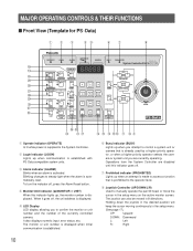
... light when the alarm is established with PS •Data compatible system units. u Prohibited indicator (PROHIBITED) Lights up when you attempt to control a system unit or camera that is already used by a higher priority operator, or when a higher priority operator selects the camera or system unit you to manually operate the pan/tilt head, or move the cursor in 8 directions. Blinking changes to access a function that is prohibited to the System Controller. t LED Display LED display...
... light when the alarm is established with PS •Data compatible system units. u Prohibited indicator (PROHIBITED) Lights up when you attempt to control a system unit or camera that is already used by a higher priority operator, or when a higher priority operator selects the camera or system unit you to manually operate the pan/tilt head, or move the cursor in 8 directions. Blinking changes to access a function that is prohibited to the System Controller. t LED Display LED display...
WVCU360C User Guide
Page 13
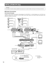
.... IN IN OUT AUDIO OUT CAMERA SW OUT VIDEO MONITOR OUT (PLAY) RS-232C DATA MODE REMOTE TIME ADJUST SERIES RECORD ALARM Branch Cable Unit Address 4 POWER ON SIGNAL GND OFF RS-485 Cable 6-conductor Modular Cable (supplied) 901 CONTROLLER No. INSTALLATIONS (PS•Data) CAUTION The installation should be used in a system. The WV-CU360C controls these system units through RS-485 communication while pictures are viewed on page 15 Monitor No. 1 Monitor No. 2 Video Signal RS-485 Signal (Panasonic Security Data Mode)
.... IN IN OUT AUDIO OUT CAMERA SW OUT VIDEO MONITOR OUT (PLAY) RS-232C DATA MODE REMOTE TIME ADJUST SERIES RECORD ALARM Branch Cable Unit Address 4 POWER ON SIGNAL GND OFF RS-485 Cable 6-conductor Modular Cable (supplied) 901 CONTROLLER No. INSTALLATIONS (PS•Data) CAUTION The installation should be used in a system. The WV-CU360C controls these system units through RS-485 communication while pictures are viewed on page 15 Monitor No. 1 Monitor No. 2 Video Signal RS-485 Signal (Panasonic Security Data Mode)
WVCU360C User Guide
Page 19
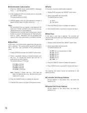
... procedure also resets all other units connected in [SUSrP], and note down the registered password for future reference. • Powering up the controller while holding down numeric buttons 2, 4 and 5 simultaneously will delay the response time (e.g., the time until an activated alarm is None. Display [LJAit] and press the CAM/SET button twice. 2. Press the ESC button to go back to the previous menu. q System Unit-Group Address...
... procedure also resets all other units connected in [SUSrP], and note down the registered password for future reference. • Powering up the controller while holding down numeric buttons 2, 4 and 5 simultaneously will delay the response time (e.g., the time until an activated alarm is None. Display [LJAit] and press the CAM/SET button twice. 2. Press the ESC button to go back to the previous menu. q System Unit-Group Address...

WVCU360C User Guide
Page 20
... CAM/SET button. on ] or [UC-oF]. 2. A frequently used system unit can occur in normal operation. Repeat above description for Unit A button Assignment. Press the ESC button to go back to the previous menu. q Unit A button Assignment In this menu, a 5-digit password for administrator certification is registered. 1. Press the ESC button to go back to the previous menu. Available password digits: 00000-99999 3. The next 2 digits are blinking. 4. Select an "A number" entering a number...
... CAM/SET button. on ] or [UC-oF]. 2. A frequently used system unit can occur in normal operation. Repeat above description for Unit A button Assignment. Press the ESC button to go back to the previous menu. q Unit A button Assignment In this menu, a 5-digit password for administrator certification is registered. 1. Press the ESC button to go back to the previous menu. Available password digits: 00000-99999 3. The next 2 digits are blinking. 4. Select an "A number" entering a number...

WVCU360C User Guide
Page 21
.../SET button to start cleaning. When Off is displayed, check connections, switch settings, etc., of the system unit. 01-on ] or [01-oF]. 2. Picture viewing is disconnected. 5. Press the CAM/SET button to the previous menu. 21 To stop the test in the left part of the LCD display the unit number under test while 2 animated digits appear at right display the number of the last unit tested is displayed without animation. 4. Enter a 2-digit number...
.../SET button to start cleaning. When Off is displayed, check connections, switch settings, etc., of the system unit. 01-on ] or [01-oF]. 2. Picture viewing is disconnected. 5. Press the CAM/SET button to the previous menu. 21 To stop the test in the left part of the LCD display the unit number under test while 2 animated digits appear at right display the number of the last unit tested is displayed without animation. 4. Enter a 2-digit number...

WVCU360C User Guide
Page 25
... Camera) • Camera functions (Combination Camera) The selected camera number can be incremented or decremented by one if the system unit is not compatible with the camera switching feature. 1. The following functions are connected to a system unit (e.g., a Video Multiplexer) to control. 2. Press the EL-ZOOM/+ button to turn the shift indicator on. 2. Press the SHIFT button to increment or the STILL/- Press the CAM/SET button. Select a system unit connected to the camera whose picture...
... Camera) • Camera functions (Combination Camera) The selected camera number can be incremented or decremented by one if the system unit is not compatible with the camera switching feature. 1. The following functions are connected to a system unit (e.g., a Video Multiplexer) to control. 2. Press the EL-ZOOM/+ button to turn the shift indicator on. 2. Press the SHIFT button to increment or the STILL/- Press the CAM/SET button. Select a system unit connected to the camera whose picture...

WVCU360C User Guide
Page 34
... s Alarm Operation When the WV-CU360C receives an alarm signal from blinking to be disturbed by alarm input as for example during setup operations. 1. Item Copy to DVD Copy Cancel DVD Copy Record Display Controller Operation SETUP SHIFT FUNCTION SETUP SHIFT FUNCTION SETUP SHIFT FUNCTION Note Equal to a selected one . q Alarm Reset 1. Notes: • Alarm reset operations including auto reset are applied to all system units, not to a selected one . • Alarm reset mode differs depending on the system unit connected to...
... s Alarm Operation When the WV-CU360C receives an alarm signal from blinking to be disturbed by alarm input as for example during setup operations. 1. Item Copy to DVD Copy Cancel DVD Copy Record Display Controller Operation SETUP SHIFT FUNCTION SETUP SHIFT FUNCTION SETUP SHIFT FUNCTION Note Equal to a selected one . q Alarm Reset 1. Notes: • Alarm reset operations including auto reset are applied to all system units, not to a selected one . • Alarm reset mode differs depending on the system unit connected to...

WVCU360C User Guide
Page 40
... setting in the setup menu. !1 Auto Focus button (AUTO FOCUS) Activates the auto focus function when the specified camera with the camera pictures on the monitor screen for more than two (2) seconds suspends activation of the alarm without changing the current alarm mode setup. During the setup, this button is used as connector for display on the multiscreen monitor. Note: When REC OUT of the Video Multiplexer is selected. @0 VTR (VCR)/Camera selection button...
... setting in the setup menu. !1 Auto Focus button (AUTO FOCUS) Activates the auto focus function when the specified camera with the camera pictures on the monitor screen for more than two (2) seconds suspends activation of the alarm without changing the current alarm mode setup. During the setup, this button is used as connector for display on the multiscreen monitor. Note: When REC OUT of the Video Multiplexer is selected. @0 VTR (VCR)/Camera selection button...
WVCU360C User Guide
Page 46
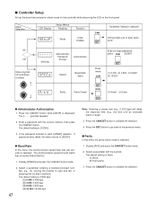
... a slower rate (e.g., 2 400 bps) will delay the response time (e.g., the time until an activated alarm is displayed. Display [PrtY] and press the CAM/SET button twice. 2. Menu Selection LED Display Setup Menus Reading Function Setup Initial Display CAM SET Parameter Selection (default*) LED prompts you to enter password No OK Move Joystick UP and down to [SEtUP]. The communication speed should match that of the WJ...
... a slower rate (e.g., 2 400 bps) will delay the response time (e.g., the time until an activated alarm is displayed. Display [PrtY] and press the CAM/SET button twice. 2. Menu Selection LED Display Setup Menus Reading Function Setup Initial Display CAM SET Parameter Selection (default*) LED prompts you to enter password No OK Move Joystick UP and down to [SEtUP]. The communication speed should match that of the WJ...

WVCU360C User Guide
Page 53
... another operation button activates a specific function. @0 Alarm Acknowledgment and Reset button (ACK/RESET) Cancels an activated alarm. SET: Executes the currently highlighted setting in the setup menu of the Matrix Switcher and opens a submenu. !5 Numeric buttons (0 - 9) These buttons are also used to the desired preset position. It also enables the CAM MENU button and SET UP button to turn the Auxiliary switches for the Receiver, Wiper and Defroster. Press this button. !4 Camera/Set button (CAM (SET)) CAM: Used for camera...
... another operation button activates a specific function. @0 Alarm Acknowledgment and Reset button (ACK/RESET) Cancels an activated alarm. SET: Executes the currently highlighted setting in the setup menu of the Matrix Switcher and opens a submenu. !5 Numeric buttons (0 - 9) These buttons are also used to the desired preset position. It also enables the CAM MENU button and SET UP button to turn the Auxiliary switches for the Receiver, Wiper and Defroster. Press this button. !4 Camera/Set button (CAM (SET)) CAM: Used for camera...

WVCU360C User Guide
Page 56
... FAR L R ZOOM TELE WIDE DOWN s DIP Switch Setting (For WJ-SX350) An 8-bit DIP switch mounted on the rear panel specifies the communication mode, etc. q DATA Port Connection (For WJ-SX350) Data ports are connected with an asterisk *. 78 456 23 901 CONTROLLER No. Note: When using cables other than those supplied, make sure to use shielded 4-wire twisted pair cable suitable for RS-485 communication. • Internal Diagram No.
... FAR L R ZOOM TELE WIDE DOWN s DIP Switch Setting (For WJ-SX350) An 8-bit DIP switch mounted on the rear panel specifies the communication mode, etc. q DATA Port Connection (For WJ-SX350) Data ports are connected with an asterisk *. 78 456 23 901 CONTROLLER No. Note: When using cables other than those supplied, make sure to use shielded 4-wire twisted pair cable suitable for RS-485 communication. • Internal Diagram No.
WVCU360C User Guide
Page 59
... check mode of the WJSX350 and the controller must be the same, otherwise data communications will delay the response time (e.g., the time until an activated alarm is valid, [SPEED] appears. Enter a password using the numeric buttons, then press the CAM/SET button. Press the CAM/SET button to the [SPEED] menu. If the password entered is reset). 3. If password entry failed, the menu returns to the [SPEED] menu. The default setting...
... check mode of the WJSX350 and the controller must be the same, otherwise data communications will delay the response time (e.g., the time until an activated alarm is valid, [SPEED] appears. Enter a password using the numeric buttons, then press the CAM/SET button. Press the CAM/SET button to the [SPEED] menu. If the password entered is reset). 3. If password entry failed, the menu returns to the [SPEED] menu. The default setting...

WVCU360C User Guide
Page 70
s DIP Switch Setting An 8-bit DIP switch mounted on the rear panel specifies communication mode, etc. Remove the DC plug from CU360 3 times s Controller Number Setting Set this switch always to 1 when using the System Controller in a home run (one to one) fashion. • Bit 6 should be set to OFF* (Operator) normally, or ON (Administrator) when setting up from the rear of the controller. 2. q Switch Setting Procedures Set the MODE DIP switch and CONTROLLER NO. switch as...
s DIP Switch Setting An 8-bit DIP switch mounted on the rear panel specifies communication mode, etc. Remove the DC plug from CU360 3 times s Controller Number Setting Set this switch always to 1 when using the System Controller in a home run (one to one) fashion. • Bit 6 should be set to OFF* (Operator) normally, or ON (Administrator) when setting up from the rear of the controller. 2. q Switch Setting Procedures Set the MODE DIP switch and CONTROLLER NO. switch as...

WVCU360C User Guide
Page 72
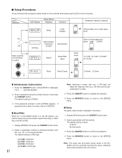
... second) is selected. 1. Menu Selection LED Display Setup Menus Reading Function Setup Initial Display CAM SET Parameter Selection (default*) LED prompts you to enter password No OK Move Joystick UP and down to validate the selection. 4. The default setting is None. The default setting is reset). 3. Press the CAMERA (ENTER) button to select blinking Administrator Password Prompt Authorization Speed Baud Rate (bps) Enter a 5-digit password, press CAM (12345*) Press...
... second) is selected. 1. Menu Selection LED Display Setup Menus Reading Function Setup Initial Display CAM SET Parameter Selection (default*) LED prompts you to enter password No OK Move Joystick UP and down to validate the selection. 4. The default setting is None. The default setting is reset). 3. Press the CAMERA (ENTER) button to select blinking Administrator Password Prompt Authorization Speed Baud Rate (bps) Enter a 5-digit password, press CAM (12345*) Press...
WVCU360C User Guide
Page 73
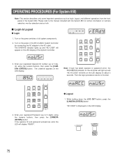
... the WV-CU360C System Controller by connecting the AC adapter to the AC outlet. The OPERATE indicator lights up and "NO ACCESS" will blink on the LED display. Enter your registered Password (up to 5 digits) using the numeric buttons, then press the [CAMERA (ENTER)] button. q Logout 1. "NO USER" is displayed on the power switches of the System Controller. 3. Then the login procedure returns to the manual included with the System 850 for...
... the WV-CU360C System Controller by connecting the AC adapter to the AC outlet. The OPERATE indicator lights up and "NO ACCESS" will blink on the LED display. Enter your registered Password (up to 5 digits) using the numeric buttons, then press the [CAMERA (ENTER)] button. q Logout 1. "NO USER" is displayed on the power switches of the System Controller. 3. Then the login procedure returns to the manual included with the System 850 for...


