
FV10NLF1 User Guide
Page 1
... 2 Description 2 Dimensions 3 Specifications_ 3 Unpacking 3 General Safety Information 4 InstallationI (HorizontallyBetweenJoists) 5-6 InstallationII (On Ceilings/Joists).. 7 InstallationIII (VerticallyOn Joists OrPillars) 8 Maintenance 9 Product Service g INSTALLATION INSTRUCTIONS IN-LINE Fan FV-10NLF1 FV-20NLF1 FV-20NLF1 FV-40NLF1 Panasonic READ AND SAVE THESE INSTRUCTIONS Please readtheinstructionscarefulybeforeattemptingto install,operate or servicethePanasonicIN-UNE Fan.Failure tocomplywithinstructions could resultin personal injuryand/orpropertydamage.
... 2 Description 2 Dimensions 3 Specifications_ 3 Unpacking 3 General Safety Information 4 InstallationI (HorizontallyBetweenJoists) 5-6 InstallationII (On Ceilings/Joists).. 7 InstallationIII (VerticallyOn Joists OrPillars) 8 Maintenance 9 Product Service g INSTALLATION INSTRUCTIONS IN-LINE Fan FV-10NLF1 FV-20NLF1 FV-20NLF1 FV-40NLF1 Panasonic READ AND SAVE THESE INSTRUCTIONS Please readtheinstructionscarefulybeforeattemptingto install,operate or servicethePanasonicIN-UNE Fan.Failure tocomplywithinstructions could resultin personal injuryand/orpropertydamage.
FV10NLF1 User Guide
Page 2
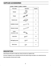
It also incorporates a therms cutout for safety. 2 The motor is designed to have an extended service life with reduced energy consumption, and a reduced noise level. SUPPLIED ACCESSORIES FV-IONLF1 FV-20NLF1 FV4ONLF1 FV4ONLF1 Part name Illustration Bracket Hanger Bracket cover Installation bracket Extension bracket Holder (asserrizisd on body) Long screw Sett-tapping screw Short screw 01,11 a sic l CISZt i. (i: 7' 4,:1 P C' Quantity 2 1 2 2 2 2 10 12 4 DESCRIPTION These Panasonic IN.LINE Fan models use a sirocco fan driven by a capaPtor motor.
It also incorporates a therms cutout for safety. 2 The motor is designed to have an extended service life with reduced energy consumption, and a reduced noise level. SUPPLIED ACCESSORIES FV-IONLF1 FV-20NLF1 FV4ONLF1 FV4ONLF1 Part name Illustration Bracket Hanger Bracket cover Installation bracket Extension bracket Holder (asserrizisd on body) Long screw Sett-tapping screw Short screw 01,11 a sic l CISZt i. (i: 7' 4,:1 P C' Quantity 2 1 2 2 2 2 10 12 4 DESCRIPTION These Panasonic IN.LINE Fan models use a sirocco fan driven by a capaPtor motor.
FV10NLF1 User Guide
Page 3
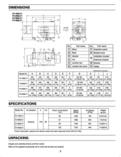
...Motor 0 Inspectionpanel • e Body (a) Adaper ® BakkeGOYS! ..., Installationbracket 0 Fan CV Extension bracket e Jordanbox 0 Bracket e ® Junctionbox cover Holder ModelNo. Part name No. Refer b the supplied accessories list to verify that all pans are present. 3 Oa.t a1 10 0 NO. Aidirection V HZ Power consumpbon ( ky ) Sped (mg FV-10NLF1 36 FV-20NLN 57 Exhaust...(97/16) 38.1 (I •. Speed and air delete, values have been maenad at Sum WG (02' WO) An clayey (CFM) 120 240 340 440 MOON 00004 8.3(13...(07 11/18) 085116) SPECIFICATIONS ModelNO.
...Motor 0 Inspectionpanel • e Body (a) Adaper ® BakkeGOYS! ..., Installationbracket 0 Fan CV Extension bracket e Jordanbox 0 Bracket e ® Junctionbox cover Holder ModelNo. Part name No. Refer b the supplied accessories list to verify that all pans are present. 3 Oa.t a1 10 0 NO. Aidirection V HZ Power consumpbon ( ky ) Sped (mg FV-10NLF1 36 FV-20NLN 57 Exhaust...(97/16) 38.1 (I •. Speed and air delete, values have been maenad at Sum WG (02' WO) An clayey (CFM) 120 240 340 440 MOON 00004 8.3(13...(07 11/18) 085116) SPECIFICATIONS ModelNO.
FV10NLF1 User Guide
Page 4
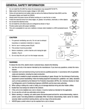
... parts with all local electrical and safety codes as well as those published by qualified person(s) in accordance with proper ventilation. 9. When cutting or drilling into a wall or ceiling, do not damage ele:trical wiring and other objects. 8. Do not install this unit only in Fig.A. 8. Sufficient air is facing the right direction. (Flf).0) 5. This product mum go grounded. E. Use...
... parts with all local electrical and safety codes as well as those published by qualified person(s) in accordance with proper ventilation. 9. When cutting or drilling into a wall or ceiling, do not damage ele:trical wiring and other objects. 8. Do not install this unit only in Fig.A. 8. Sufficient air is facing the right direction. (Flf).0) 5. This product mum go grounded. E. Use...
FV10NLF1 User Guide
Page 5
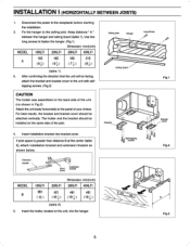
... center (table 2), attach installation bracket and extension bracket as shown below. INSTALLATION I ) 3. Use two long screws to fasten the hanger. (Flg.1) Dimension: mm(inch) MODEL 1ONLFI 2061LFI 3ONLF1 4ONLFI 165 165 185 215 A (6+) (8f) (7I) (Of) (table I (HORIZONTALLY BETWEEN JOISTS) 1. Flo Flp.2 Flea 5 After confirming the direction that the unit will be facing, attach the bracket and tracket cover to the panel of...
... center (table 2), attach installation bracket and extension bracket as shown below. INSTALLATION I ) 3. Use two long screws to fasten the hanger. (Flg.1) Dimension: mm(inch) MODEL 1ONLFI 2061LFI 3ONLF1 4ONLFI 165 165 185 215 A (6+) (8f) (7I) (Of) (table I (HORIZONTALLY BETWEEN JOISTS) 1. Flo Flp.2 Flea 5 After confirming the direction that the unit will be facing, attach the bracket and tracket cover to the panel of...
FV10NLF1 User Guide
Page 6
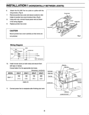
... cover andsecureconduit or wire holder lo junction box cover knockout hole. (Fig.5) 8. CAUTION Mount junctionbox cover carefully so that wires are not pinched. Consult table3 for the appropriateduct sizes. Installcircularducts (on Carmel:et Sawn Fie.a Wiring Diagram Pad / 5* aw ./.7" %Ns Noun/ Est 10. Connectpower toe to a joist or a pillar with tape or clamps. Replacejunction box cover. a uana tames Mak • F10.5 6 Dimension: mm(inch) MODEL...
... cover andsecureconduit or wire holder lo junction box cover knockout hole. (Fig.5) 8. CAUTION Mount junctionbox cover carefully so that wires are not pinched. Consult table3 for the appropriateduct sizes. Installcircularducts (on Carmel:et Sawn Fie.a Wiring Diagram Pad / 5* aw ./.7" %Ns Noun/ Est 10. Connectpower toe to a joist or a pillar with tape or clamps. Replacejunction box cover. a uana tames Mak • F10.5 6 Dimension: mm(inch) MODEL...
FV10NLF1 User Guide
Page 7
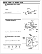
Extend installation bracket and put the unit on both ends) and securethem with tape or clamps. Using wire nuts. Consult table 3 for the appropriatedud saes Dimension: mm(inch) MODEL I0NLFI 2ONLEI 3ONLFI 40NLF1 102 152 152 203 duct d (4) (6) (6) (8) ESSI 0~ Cara At Ws (table 3) 7 ffres aw FIg.? INSTALLATIONII (ON CEILINGS/JOISTS) I. CAUTION Mount function box cover carefully so that wires we not pinched...
Extend installation bracket and put the unit on both ends) and securethem with tape or clamps. Using wire nuts. Consult table 3 for the appropriatedud saes Dimension: mm(inch) MODEL I0NLFI 2ONLEI 3ONLFI 40NLF1 102 152 152 203 duct d (4) (6) (6) (8) ESSI 0~ Cara At Ws (table 3) 7 ffres aw FIg.? INSTALLATIONII (ON CEILINGS/JOISTS) I. CAUTION Mount function box cover carefully so that wires we not pinched...
FV10NLF1 User Guide
Page 8
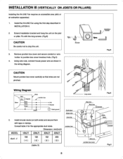
... with the long screws. (Fog.8) CAUTION Be careful not to junctionbox cover knockouthole. (Fig.5) 4. Arm 3. Using wire nuts, connect house power wire as shown in INSTALLATIONII. 2. Installcircular ducts(on the joist or paler. Consult table 3 for the appropriateduct sizes. Install the IN-LINE Fan using the first step described in the wiring diagram. Wiring Diagram Red Cl qe" of tagnew Fled**, war Blue re 5. Remove junctionbox cover and secure conduit...
... with the long screws. (Fog.8) CAUTION Be careful not to junctionbox cover knockouthole. (Fig.5) 4. Arm 3. Using wire nuts, connect house power wire as shown in INSTALLATIONII. 2. Installcircular ducts(on the joist or paler. Consult table 3 for the appropriateduct sizes. Install the IN-LINE Fan using the first step described in the wiring diagram. Wiring Diagram Red Cl qe" of tagnew Fled**, war Blue re 5. Remove junctionbox cover and secure conduit...

FV10NLF1 User Guide
Page 9
.... 3. S. However, should ycur unit ever require service,a nationwidesystem of covers. MAINTENANCE WARNING Disconnectpowerline beforeproceedingwith repairsOr maintenance. Wipedrywith a cloth(donot wipe thermal insulationpans inside the fan's body using a vacuum Sooner. (Fig.10) 4. NJ 07094, USA httpj/www.panasonic.com PANASONIC CANADAINC. 5770 AmblerDrive, Mississauga, Ontario L4W 2T3, CANADA Mtp://www.panasonic.ca 9 =arc 0 Remove inspectionpanel (takeoff the screwsandpull). (Fig...
.... 3. S. However, should ycur unit ever require service,a nationwidesystem of covers. MAINTENANCE WARNING Disconnectpowerline beforeproceedingwith repairsOr maintenance. Wipedrywith a cloth(donot wipe thermal insulationpans inside the fan's body using a vacuum Sooner. (Fig.10) 4. NJ 07094, USA httpj/www.panasonic.com PANASONIC CANADAINC. 5770 AmblerDrive, Mississauga, Ontario L4W 2T3, CANADA Mtp://www.panasonic.ca 9 =arc 0 Remove inspectionpanel (takeoff the screwsandpull). (Fig...


