Installation Instructions
Page 1
Table of Contents Supplied Accessories Description Dimensions Specifications Unpacking General Safety Information Wiring diagram Installation I ( Joist Mounting-I ) Installation II ( Joist Mounting-II ) Installation ( I -Joist Mounting ) Installation IV( Between Joist Mounting ) Installation V ( Wooden Header ) Installation VI( In Existing Construction ) Maintenance Practical Guide to install, operate or service the Panasonic Ventilating Fan. Please retain this booklet for future reference. INSTALLATION INSTRUCTIONS Ventilating Fan FV-08VQL4 FV-11VQL4 FV-1 5VQL4 Panasonid READ AND ...
Table of Contents Supplied Accessories Description Dimensions Specifications Unpacking General Safety Information Wiring diagram Installation I ( Joist Mounting-I ) Installation II ( Joist Mounting-II ) Installation ( I -Joist Mounting ) Installation IV( Between Joist Mounting ) Installation V ( Wooden Header ) Installation VI( In Existing Construction ) Maintenance Practical Guide to install, operate or service the Panasonic Ventilating Fan. Please retain this booklet for future reference. INSTALLATION INSTRUCTIONS Ventilating Fan FV-08VQL4 FV-11VQL4 FV-1 5VQL4 Panasonid READ AND ...
Installation Instructions
Page 2
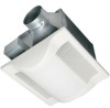
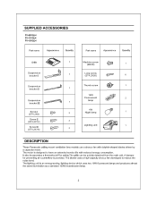
... bracket III 1 Screw I (ST4.2X8) 0 7) 2 Screw II (ST4.2X12) 0D 2 Screw III 2 (ST4.2X16) Part name Appearance Quantity Machine screw (M4X8) 0) 1 Long screw (ST4.2X20) 6 Thumb screw 0" 1 18W 1 Fluorescent 2 lamp • 4W Night lamp 1 Lighting unit 1 DESCRIPTION These Panasonic ceiling mount ventilation fans models use a sirocco fan with reduced energy consumption. The motor is designed to reduce the noise level. It also incorporates a thermal-cutoff for preventing air counterflow...
... bracket III 1 Screw I (ST4.2X8) 0 7) 2 Screw II (ST4.2X12) 0D 2 Screw III 2 (ST4.2X16) Part name Appearance Quantity Machine screw (M4X8) 0) 1 Long screw (ST4.2X20) 6 Thumb screw 0" 1 18W 1 Fluorescent 2 lamp • 4W Night lamp 1 Lighting unit 1 DESCRIPTION These Panasonic ceiling mount ventilation fans models use a sirocco fan with reduced energy consumption. The motor is designed to reduce the noise level. It also incorporates a thermal-cutoff for preventing air counterflow...
Installation Instructions
Page 3
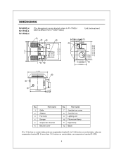
... 1101 00EME755511% 3 10 1 4 (261) 3 1/2 (90) [3 7/8 (100)] No. Part name 1 Grille 2 Adaptor 3 Fan body 4 Damper 5 Suspension bracket 6 Bracket cover No. Part name 7 Junction box cover 8 Junction box 9 Lighting unit 10 Fluorescent lamp 11 Night lamp 12 Blade (For 16 inches on center joists,only use suspension bracket I, for 19.2 inches on center joists, only use suspension bracket III, If more than 19.2 inches on center joists, use suspension bracket II & IT) 3
... 1101 00EME755511% 3 10 1 4 (261) 3 1/2 (90) [3 7/8 (100)] No. Part name 1 Grille 2 Adaptor 3 Fan body 4 Damper 5 Suspension bracket 6 Bracket cover No. Part name 7 Junction box cover 8 Junction box 9 Lighting unit 10 Fluorescent lamp 11 Night lamp 12 Blade (For 16 inches on center joists,only use suspension bracket I, for 19.2 inches on center joists, only use suspension bracket III, If more than 19.2 inches on center joists, use suspension bracket II & IT) 3
Installation Instructions
Page 4
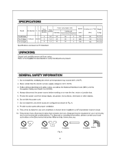
... mercury. SPECIFICATIONS Model Power consumption (W) Air direction V Hz Duct diameter (inches) Noise (sones) Fan body Lighting unit Fluorescent lamp Night lamp Speed (rpm) Air deliver at 0.1"WG Weight (cfm) lb.(kg) FV-08VQL4 4 0.3 25 36 4 765 FV-11VQL4 Exhaust 120 60 4 1.0 35 36 4 890 FV-15VQL4 6 1.2 36 36 4 790 80 15.7 (7.1) 110 15.7 (7.1) 150 16.5 (7.5) Specifications are based on or near the fan, motor or junction box. 5. A. 8. This...
... mercury. SPECIFICATIONS Model Power consumption (W) Air direction V Hz Duct diameter (inches) Noise (sones) Fan body Lighting unit Fluorescent lamp Night lamp Speed (rpm) Air deliver at 0.1"WG Weight (cfm) lb.(kg) FV-08VQL4 4 0.3 25 36 4 765 FV-11VQL4 Exhaust 120 60 4 1.0 35 36 4 890 FV-15VQL4 6 1.2 36 36 4 790 80 15.7 (7.1) 110 15.7 (7.1) 150 16.5 (7.5) Specifications are based on or near the fan, motor or junction box. 5. A. 8. This...
Installation Instructions
Page 5
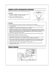
For general ventilating use in Canada only.) WIRING DIAGRAM Fan body Motor Moteur Red White _L Capacitor Black White Green Current Fuse • Black white Electronic Ballast - B Floor WARNING: To reduce the risk of fire or electric shock, do not damage electrical wiring and other hidden utilities. If you have any solid-state control device. C. D. G. To reduce the risk of fire, electric shock or injury to persons...
For general ventilating use in Canada only.) WIRING DIAGRAM Fan body Motor Moteur Red White _L Capacitor Black White Green Current Fuse • Black white Electronic Ballast - B Floor WARNING: To reduce the risk of fire or electric shock, do not damage electrical wiring and other hidden utilities. If you have any solid-state control device. C. D. G. To reduce the risk of fire, electric shock or injury to persons...
Installation Instructions
Page 6
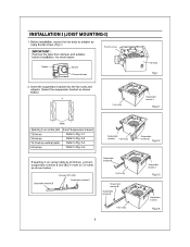
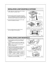
... to Fig. 2-3 Refer to Fig. 2-4 Fan body Suspension bracket I Fig.2-1 Suspension bracket I ) 1. As show below ) A 111 1 11I it it Joists Spacing A on center joists is 24 inches, connect suspension bracket II and III(C4 mark to adaptor by using thumb screw. (Fig.1) IMPORTANT : Remove the tape from damper and adaptor before installation. Before installation, secure the fan body to C4 mark) as...
... to Fig. 2-3 Refer to Fig. 2-4 Fan body Suspension bracket I Fig.2-1 Suspension bracket I ) 1. As show below ) A 111 1 11I it it Joists Spacing A on center joists is 24 inches, connect suspension bracket II and III(C4 mark to adaptor by using thumb screw. (Fig.1) IMPORTANT : Remove the tape from damper and adaptor before installation. Before installation, secure the fan body to C4 mark) as...
Installation Instructions
Page 7
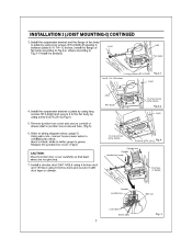
....3-1 install the product) Joist Fan body 4 Long screws (ST4.2X20) Fig.3-1 A=10 1/4-12 inches Joist 4. Refer to wiring diagram below. (page 5) Using wire nuts, connect house power wires to ventilating fan wires: black to white; Install the suspension bracket and the flange of Joist fan body according to Fig.3-2, others according to joists by using 6 inches duct) and secure it with duct tape or clamps. Replace the junction box cover. (Fig.5) CAUTION: Mount junction box cover...
....3-1 install the product) Joist Fan body 4 Long screws (ST4.2X20) Fig.3-1 A=10 1/4-12 inches Joist 4. Refer to wiring diagram below. (page 5) Using wire nuts, connect house power wires to ventilating fan wires: black to white; Install the suspension bracket and the flange of Joist fan body according to Fig.3-2, others according to joists by using 6 inches duct) and secure it with duct tape or clamps. Replace the junction box cover. (Fig.5) CAUTION: Mount junction box cover...
Installation Instructions
Page 8
Ceiling hole should be aligned with 2 screw III (ST4.2X16) and 1 machine screw (M4X8). (Fig.6) Plug connectorII Plug connectorIII 10. INSTALLATION I (JOIST MOUNTING-I) CONTINUED 8. Insert the fluorescent lamps and screw the night lamp into the receptacle II and receptacle III respectively, and secure the lighting unit to the fan unit with the edge of the flange. (Fig.6) 7 118 71 Ceiling 9. Finish ceiling work. Insert the plug connector II and plug connector III into the lighting unit.(Fig.6) Lighting unit g screw III (ST4.2X16) Machine screw Plug connector III (M4X84)
Ceiling hole should be aligned with 2 screw III (ST4.2X16) and 1 machine screw (M4X8). (Fig.6) Plug connectorII Plug connectorIII 10. INSTALLATION I (JOIST MOUNTING-I) CONTINUED 8. Insert the fluorescent lamps and screw the night lamp into the receptacle II and receptacle III respectively, and secure the lighting unit to the fan unit with the edge of the flange. (Fig.6) 7 118 71 Ceiling 9. Finish ceiling work. Insert the plug connector II and plug connector III into the lighting unit.(Fig.6) Lighting unit g screw III (ST4.2X16) Machine screw Plug connector III (M4X84)
Installation Instructions
Page 9
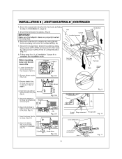
...-2 a Joist Fig.12-3 8. Remove adaptor from blower). (Fig.12-1) Joist Conduit Junction box cover Duct tape or clamps Circular duct 0 1 Fan body Slots Adaptor claws 2. Secure the fan body to receptacle(Fig.10) 7. Insert the suspension bracket into body slots. 6. Secure the fan body to adaptor by using thumb screw and plug connector to joists by using long screw V'q (ST4.2X20). (Fig.11...
...-2 a Joist Fig.12-3 8. Remove adaptor from blower). (Fig.12-1) Joist Conduit Junction box cover Duct tape or clamps Circular duct 0 1 Fan body Slots Adaptor claws 2. Secure the fan body to receptacle(Fig.10) 7. Insert the suspension bracket into body slots. 6. Secure the fan body to adaptor by using thumb screw and plug connector to joists by using long screw V'q (ST4.2X20). (Fig.11...
Installation Instructions
Page 10
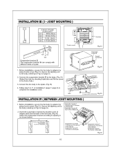
... ( BETWEEN JOIST MOUNTING ) 1. Connect the suspension bracket III to adaptor by using thumb screw (Fig.13). I -joist size and fix the screw to complete the installation work. Connect the fan body to the I (page 7-page 8) to the frame hole.) 3. Follow step 5 to 11 of the fan body. (Fig.16) (select the suspension bracket according to Fig.6 of page 8). 2. Secure the lighting unit to fan body (refering...
... ( BETWEEN JOIST MOUNTING ) 1. Connect the suspension bracket III to adaptor by using thumb screw (Fig.13). I -joist size and fix the screw to complete the installation work. Connect the fan body to the I (page 7-page 8) to the frame hole.) 3. Follow step 5 to 11 of the fan body. (Fig.16) (select the suspension bracket according to Fig.6 of page 8). 2. Secure the lighting unit to fan body (refering...
Installation Instructions
Page 11
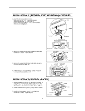
... screws. 3. Secure the suspension bracket to 11 of ceiling board. Follow step 5 to joists by using screw II (ST4.2X12). (Fig.19) 6. Adaptor 0 Fan body Junction box 13 1/4-15 3/4 (336-400) A 16 1/2-183/4 (419-480) 3-5 ( 76-126 ) 5 4/5-7 4/5 ( 48-198 4. INSTALLATION IV ( BETWEEN JOIST MOUNTING ) CONTINUED 3. Insert the fan body between joists by using long screws (ST4.2X20). (Fig.20, Fig.21) Fan body inches...
... screws. 3. Secure the suspension bracket to 11 of ceiling board. Follow step 5 to joists by using screw II (ST4.2X12). (Fig.19) 6. Adaptor 0 Fan body Junction box 13 1/4-15 3/4 (336-400) A 16 1/2-183/4 (419-480) 3-5 ( 76-126 ) 5 4/5-7 4/5 ( 48-198 4. INSTALLATION IV ( BETWEEN JOIST MOUNTING ) CONTINUED 3. Insert the fan body between joists by using long screws (ST4.2X20). (Fig.20, Fig.21) Fan body inches...
Installation Instructions
Page 12
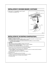
... wiring before installation. Wiring can be run to Fig.6 of page 8. (6) Install fan body. 2. Follow step 5 to complete the installation work can be done and that : 1. Adaptor Circular duct 88 a 8 6 Long screws (ST4.2X20) Conduit Junction box 0 Wire nut Lead wires Green wires Fig.21 INSTALLATION VI ( IN EXISTING CONSTRUCTION ) 1. Installing the fan body in existing construction. No wiring or other obstructions will not interfere with installation. (2) Remove ceiling...
... wiring before installation. Wiring can be run to Fig.6 of page 8. (6) Install fan body. 2. Follow step 5 to complete the installation work can be done and that : 1. Adaptor Circular duct 88 a 8 6 Long screws (ST4.2X20) Conduit Junction box 0 Wire nut Lead wires Green wires Fig.21 INSTALLATION VI ( IN EXISTING CONSTRUCTION ) 1. Installing the fan body in existing construction. No wiring or other obstructions will not interfere with installation. (2) Remove ceiling...
Installation Instructions
Page 13
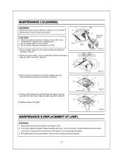
....24 Fig.25 MAINTENANCE 11 (REPLACEMENT OF LAMP) WARNING: 1. To remove lamp, grasp at base and move back and force to enter motor. 3. The lamp's glass is fragile. Disconnect power source before working on unit. Remove grille. (Squeeze mounting spring and pull down carefully.) (Fig.22) 2. Using a cloth dampened with new cloth.) (Fig.23) Grille Slot Mounting spring 1 Fig. 22 3. Please handle...
....24 Fig.25 MAINTENANCE 11 (REPLACEMENT OF LAMP) WARNING: 1. To remove lamp, grasp at base and move back and force to enter motor. 3. The lamp's glass is fragile. Disconnect power source before working on unit. Remove grille. (Squeeze mounting spring and pull down carefully.) (Fig.22) 2. Using a cloth dampened with new cloth.) (Fig.23) Grille Slot Mounting spring 1 Fig. 22 3. Please handle...
Installation Instructions
Page 14
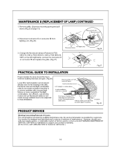
... directly over the fan housing in the attic. Our efficient, cool-running motors and our fluorescent bulbs do not create excessive heat that is designed and manufactured to support your unit ever require service, a nationwide system of Covers. Insulation. Your product is a common problem with backdraft flap(s). Clamps plus tape at all flex joints. Disconnect connector II or connector DI from lighting...
... directly over the fan housing in the attic. Our efficient, cool-running motors and our fluorescent bulbs do not create excessive heat that is designed and manufactured to support your unit ever require service, a nationwide system of Covers. Insulation. Your product is a common problem with backdraft flap(s). Clamps plus tape at all flex joints. Disconnect connector II or connector DI from lighting...


