
FV11VH2 User Guide
Page 1
FV-11VH2 FV-11VHL2 FV-11VHL2 Thank you very much for having purchased our Ventilating Fan. I II III Maintenance I (Cleaning) Maintenance II (Replacement of lamp) back cover back cover FV-11VH2 Ventilating Fan Model No.
FV-11VH2 FV-11VHL2 FV-11VHL2 Thank you very much for having purchased our Ventilating Fan. I II III Maintenance I (Cleaning) Maintenance II (Replacement of lamp) back cover back cover FV-11VH2 Ventilating Fan Model No.

FV11VH2 User Guide
Page 2
... unit from carton. The motor is designed to have been added for this unit is provided. The blower uses a high-capacity sirocco fan developed to verify that all parts are present. The grille covering the main body is an energy-saving, lighting device which uses two...-11VHL2). SUPPLIED ACCESSORIES FOR MODEL FV-11VH2 FOR MODEL FV-11VH2 POURLE MODELE FV-11VHL2 POURLE MODELE FV-11VHL2 DESCRIPTION The Panasonic ceiling mount ventilating fans uses a sirocco fan driven by a capacitor motor. Refer to the Supplied Accessories list to reduce the noise level. A thermostat and thermal cut...
... unit from carton. The motor is designed to have been added for this unit is provided. The blower uses a high-capacity sirocco fan developed to verify that all parts are present. The grille covering the main body is an energy-saving, lighting device which uses two...-11VHL2). SUPPLIED ACCESSORIES FOR MODEL FV-11VH2 FOR MODEL FV-11VH2 POURLE MODELE FV-11VHL2 POURLE MODELE FV-11VHL2 DESCRIPTION The Panasonic ceiling mount ventilating fans uses a sirocco fan driven by a capacitor motor. Refer to the Supplied Accessories list to reduce the noise level. A thermostat and thermal cut...

FV11VH2 User Guide
Page 5
...on accidentally. If you have any solid-state control device. Not to be done by the manufacturer. WIRING DIAGRAM Circulating fan unit Black Motor(C) Red White Black PCB White Fuse Thermal cut-off (20A) (230oF (110oC)) Heater (1400W) Thermostat (140oF (60Co )) ...D. Before servicing or cleaning unit, switch power off Black (20A) (230oF (110oC)) Heater (1400W) Thermostat (140oF (60oC)) White Ventilating fan unit Motor(V) Red White Black Capacitor White Fuse (3.15A) Black Lighting unit Fluorescent lamp Electronic ballast Black White White Black Black White Black Junction...
...on accidentally. If you have any solid-state control device. Not to be done by the manufacturer. WIRING DIAGRAM Circulating fan unit Black Motor(C) Red White Black PCB White Fuse Thermal cut-off (20A) (230oF (110oC)) Heater (1400W) Thermostat (140oF (60Co )) ...D. Before servicing or cleaning unit, switch power off Black (20A) (230oF (110oC)) Heater (1400W) Thermostat (140oF (60oC)) White Ventilating fan unit Motor(V) Red White Black Capacitor White Fuse (3.15A) Black Lighting unit Fluorescent lamp Electronic ballast Black White White Black Black White Black Junction...
FV11VH2 User Guide
Page 6
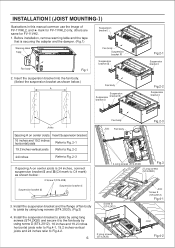
... the damper. (Fig.1) Suspension bracket Warning label Tape Fan body Suspension bracket Fan body Fig.1 Suspension bracket 2. Insert the suspension bracket into the fan body. (Select the suspension bracket as shown below.) Fan body Suspension Suspension bracket bracket Fig.2-1 Suspension bracket Fig.2-2... Suspension bracket Joists 16 inches and 19.2 inches horizontal joists Fan body Joist Fan body Fig.2-3 Suspension bracket 2 Screw (ST4.2X8) Suspension bracket (Fig.3) 4 Long screws (ST4.2X20) Fig.3 2 Long...
... the damper. (Fig.1) Suspension bracket Warning label Tape Fan body Suspension bracket Fan body Fig.1 Suspension bracket 2. Insert the suspension bracket into the fan body. (Select the suspension bracket as shown below.) Fan body Suspension Suspension bracket bracket Fig.2-1 Suspension bracket Fig.2-2... Suspension bracket Joists 16 inches and 19.2 inches horizontal joists Fan body Joist Fan body Fig.2-3 Suspension bracket 2 Screw (ST4.2X8) Suspension bracket (Fig.3) 4 Long screws (ST4.2X20) Fig.3 2 Long...

FV11VH2 User Guide
Page 7
...slots as the National Electrical Code (NEC). If the grille is finished. Using UL approved wire nuts, connect house power wires to ventilating fan wires (Fig.6): Black to green. green to black; Finish ceiling work. Make sure all the local electrical safety codes. Install the ...to white; Refer to the adaptor and secure it with the edge of the flange. (Fig.8) 9. white to white Junction box Conduit Fig.6 Conduit Fan body Joist Circular duct Duct tape or clamps 7. INSTALLATION (JOIST MOUNTING- ) CONTINUED 5. Install the circular duct (4 inches) to wiring diagram (Page.5)...
...slots as the National Electrical Code (NEC). If the grille is finished. Using UL approved wire nuts, connect house power wires to ventilating fan wires (Fig.6): Black to green. green to black; Finish ceiling work. Make sure all the local electrical safety codes. Install the ...to white; Refer to the adaptor and secure it with the edge of the flange. (Fig.8) 9. white to white Junction box Conduit Fig.6 Conduit Fan body Joist Circular duct Duct tape or clamps 7. INSTALLATION (JOIST MOUNTING- ) CONTINUED 5. Install the circular duct (4 inches) to wiring diagram (Page.5)...

FV11VH2 User Guide
Page 8
Fan body Suspension bracket C Joists Adaptor Junction box Fig.12 INSTALLATION (BETWEEN JOIST MOUNTING) Illustrations in this manual common use the image of ceiling board. Before ... the tape that is securing the adapter and the damper. (Fig.1) Suspension bracket Fig.11 (Select the suspension bracket according to spacing A as shown below.) B Fan body Suspension bracket Suspension bracket Fig.11 Spacing A on center joists B 16 inches 13 1/4 ~ 15 1/2 (336~394) 19.2 inches horizontal joists 14 3/4 ~ 16 3/4 (374~425...
Fan body Suspension bracket C Joists Adaptor Junction box Fig.12 INSTALLATION (BETWEEN JOIST MOUNTING) Illustrations in this manual common use the image of ceiling board. Before ... the tape that is securing the adapter and the damper. (Fig.1) Suspension bracket Fig.11 (Select the suspension bracket according to spacing A as shown below.) B Fan body Suspension bracket Suspension bracket Fig.11 Spacing A on center joists B 16 inches 13 1/4 ~ 15 1/2 (336~394) 19.2 inches horizontal joists 14 3/4 ~ 16 3/4 (374~425...

FV11VH2 User Guide
Page 9
... Before installation, remove warning lable and the tape that is securing the adapter and the damper. (Fig.1) Ceiling joist (Fig.15, Fig.16) 11 3/8 (290) Fan body Header 19 7/8 (505) Ceiling joist Adaptor Fig.15 4. INSTALLATION (BETWEEN JOIST MOUNTING) CONTINUED Fig.13, Fig.14 2 Long screws (ST4.2X20) Joist Fig.13...
... Before installation, remove warning lable and the tape that is securing the adapter and the damper. (Fig.1) Ceiling joist (Fig.15, Fig.16) 11 3/8 (290) Fan body Header 19 7/8 (505) Ceiling joist Adaptor Fig.15 4. INSTALLATION (BETWEEN JOIST MOUNTING) CONTINUED Fig.13, Fig.14 2 Long screws (ST4.2X20) Joist Fig.13...

FV11VH2 User Guide
Page 12
... flex joints. PRACTICAL GUIDE TO INSTALLATION Properly insulate the area around the fan to duct. 2-3 ft straight run before elbow. Caulk termination to Fig.23 Dryer-hood type vent with backdraft flap (s). Insulation Fig.23 PANASONIC CONSUMER ELECTRONICS COMPANY Division de Panasonic Corporation of flexible duct helps alignment and absorbs sound. In attic...
... flex joints. PRACTICAL GUIDE TO INSTALLATION Properly insulate the area around the fan to duct. 2-3 ft straight run before elbow. Caulk termination to Fig.23 Dryer-hood type vent with backdraft flap (s). Insulation Fig.23 PANASONIC CONSUMER ELECTRONICS COMPANY Division de Panasonic Corporation of flexible duct helps alignment and absorbs sound. In attic...
