
FV-08WQ1 Owner's Manual (English)
Page 1
...FV-08WQ1 READ AND SAVE THESE INSTRUCTIONS Please read instructions carefully before attempting to comply with these instructions could result in personal injury and/or property damage. Please retain for future reference. Table of Contents Pages List of components ...2 Description ...2 Reference installation... drawing 2 Dimensions ...3 Specifications ...4 Unpacking ...4 General safety precautions 4 Installation I (In new construction 5-6 Installation II (In remodeling 7-8 Maintenance ...9-10 Product Service ...10 Failure to install, operate or service the Panasonic ...
...FV-08WQ1 READ AND SAVE THESE INSTRUCTIONS Please read instructions carefully before attempting to comply with these instructions could result in personal injury and/or property damage. Please retain for future reference. Table of Contents Pages List of components ...2 Description ...2 Reference installation... drawing 2 Dimensions ...3 Specifications ...4 Unpacking ...4 General safety precautions 4 Installation I (In new construction 5-6 Installation II (In remodeling 7-8 Maintenance ...9-10 Product Service ...10 Failure to install, operate or service the Panasonic ...
FV-08WQ1 Owner's Manual (English)
Page 2
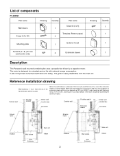
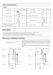
... below . It also incorporates a thermal-cutoff device for new construction only) 2 Externsion sleeve Drawing Quantity 1 1 1 1 Description This Panasonic wall mounted ventilating fan uses a propeller fan driven by a capacitor motor. When the wall thickness is designed for extended service life with ...installation drawing Wall thickness: 114.3 - 152.4 mm (4.5 - 6") No extension sleeve is easily detachable from the main unit. The motor is more than 254 mm (10"), prepare an extension sleeve with an inner diameter of 207 mm (8 5/32") and a length of components FV-08WQ1...
... below . It also incorporates a thermal-cutoff device for new construction only) 2 Externsion sleeve Drawing Quantity 1 1 1 1 Description This Panasonic wall mounted ventilating fan uses a propeller fan driven by a capacitor motor. When the wall thickness is designed for extended service life with ...installation drawing Wall thickness: 114.3 - 152.4 mm (4.5 - 6") No extension sleeve is easily detachable from the main unit. The motor is more than 254 mm (10"), prepare an extension sleeve with an inner diameter of 207 mm (8 5/32") and a length of components FV-08WQ1...
FV-08WQ1 Owner's Manual (English)
Page 4
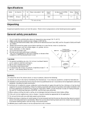
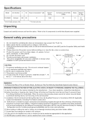
.... CAUTION: 1. This product must be grounded. 4. Use this area. Specifications Model Air direction V Hz Power consumption*1 (W) FV-08WQ1 Exhaust 120 60 17 Speed*1 (r/min.) 1340 *1 At 0.0" Static pressure, (Pa) *2 For main unit only. Do not install this unit is 120V 60 Hz. 3. If this ventilating fan where air temperature may exceed 104 °...
.... CAUTION: 1. This product must be grounded. 4. Use this area. Specifications Model Air direction V Hz Power consumption*1 (W) FV-08WQ1 Exhaust 120 60 17 Speed*1 (r/min.) 1340 *1 At 0.0" Static pressure, (Pa) *2 For main unit only. Do not install this unit is 120V 60 Hz. 3. If this ventilating fan where air temperature may exceed 104 °...
FV-08WQ1 Owner's Manual (English)
Page 5
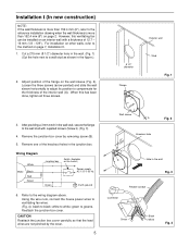
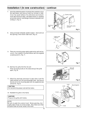
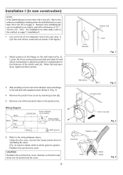
... in the wall. (Fig. 1) (Cut the hole next to compensate for the thickness of 12.7 - 16 mm (1/2 - 5/8"). When this ventilating fan can be installed on the wall sleeve (Fig. 2). Remove the junction box cover by the cover. 5 Wall sleeve A Fig. 2 13/m8"m Knockout hole B Hole in the ... wall stud with a thickness of the interior wall (A). green to white; However, this has been done, tighten all three screws. For installation on page 7, Installation II. 1. Using the wire nuts, connect the house power wires to ventilating fan wires. (Fig. 4): black to the method on other...
... in the wall. (Fig. 1) (Cut the hole next to compensate for the thickness of 12.7 - 16 mm (1/2 - 5/8"). When this ventilating fan can be installed on the wall sleeve (Fig. 2). Remove the junction box cover by the cover. 5 Wall sleeve A Fig. 2 13/m8"m Knockout hole B Hole in the ... wall stud with a thickness of the interior wall (A). green to white; However, this has been done, tighten all three screws. For installation on page 7, Installation II. 1. Using the wire nuts, connect the house power wires to ventilating fan wires. (Fig. 4): black to the method on other...
FV-08WQ1 Owner's Manual (English)
Page 6
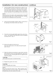
... four screws or nails. Reattach the grille to paint the exterior hood. NOTE: Be sure to the frame. Press the spring locks on the surface. Installation I (In new construction) - Using enclosed template (pattern paper), mark and cut the opening in . (Fig. 5) Exterior hood 8. Press the mounting plate tightly against the wall...
... four screws or nails. Reattach the grille to paint the exterior hood. NOTE: Be sure to the frame. Press the spring locks on the surface. Installation I (In new construction) - Using enclosed template (pattern paper), mark and cut the opening in . (Fig. 5) Exterior hood 8. Press the mounting plate tightly against the wall...
FV-08WQ1 Owner's Manual (English)
Page 7
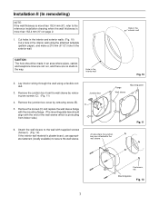
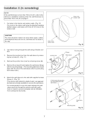
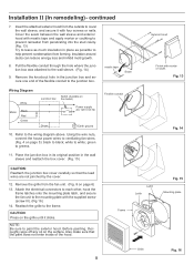
A hole where the junction box was attached to the reference installation drawing when the wall thickness is more than 152.4 mm (6") on page 2. 1. Remove the junction box cover by removing two screws (C). (Fig. 11) 4. Hole in ... align with supplied screws (Screw I). (Fig. 12) If the interior wall material is plaster board, use appropriate fasteners (locally available) to secure the wall sleeve. Installation II (In remodeling) NOTE: If the wall thickness is more than 152.4 mm (6"), refer to the wall sleeve. Remove the screws (D) and replace the wall...
A hole where the junction box was attached to the reference installation drawing when the wall thickness is more than 152.4 mm (6") on page 2. 1. Remove the junction box cover by removing two screws (C). (Fig. 11) 4. Hole in ... align with supplied screws (Screw I). (Fig. 12) If the interior wall material is plaster board, use appropriate fasteners (locally available) to secure the wall sleeve. Installation II (In remodeling) NOTE: If the wall thickness is more than 152.4 mm (6"), refer to the wall sleeve. Remove the screws (D) and replace the wall...

FV-08WQ1 Owner's Manual (English)
Page 8
... the junction box cover carefully so that the paint does not enter inside of the flexible conduit to the mounting plate with mortar or caulk. Installation II (In remodeling) - Refer to white; white to the wiring diagram above. Attach the electrical connectors to each other, hook the frame latches onto the...
... the junction box cover carefully so that the paint does not enter inside of the flexible conduit to the mounting plate with mortar or caulk. Installation II (In remodeling) - Refer to white; white to the wiring diagram above. Attach the electrical connectors to each other, hook the frame latches onto the...
Installation Instructions
Page 1
... Product Service ...10 Please retain for future reference. INSTALLATION INSTRUCTIONS Through the Wall Fan "Whisper Wall" Ventilating Fan FV-08WQ1 READ AND SAVE THESE INSTRUCTIONS Please read instructions carefully before attempting to comply with these instructions could result in personal injury and/or property damage. Failure to install, operate or service the Panasonic Ventilating Fan.
... Product Service ...10 Please retain for future reference. INSTALLATION INSTRUCTIONS Through the Wall Fan "Whisper Wall" Ventilating Fan FV-08WQ1 READ AND SAVE THESE INSTRUCTIONS Please read instructions carefully before attempting to comply with these instructions could result in personal injury and/or property damage. Failure to install, operate or service the Panasonic Ventilating Fan.
Installation Instructions
Page 2
...Reference installation drawing Wall thickness: 114.3 - 152.4 mm (4.5 - 6") No extension sleeve is easily detachable from the main unit. When the wall thickness is designed for extended service life with an inner diameter of 207 mm (8 5/32") and a length of components FV-08WQ1 ... Indoor It also incorporates a thermal-cutoff device for new construction only) 2 Externsion sleeve Drawing Quantity 1 1 1 1 Description This Panasonic wall mounted ventilating fan uses a propeller fan driven by a capacitor motor. Insulation around ducts can reduce energy loss and inhibit mold growth...
...Reference installation drawing Wall thickness: 114.3 - 152.4 mm (4.5 - 6") No extension sleeve is easily detachable from the main unit. When the wall thickness is designed for extended service life with an inner diameter of 207 mm (8 5/32") and a length of components FV-08WQ1 ... Indoor It also incorporates a thermal-cutoff device for new construction only) 2 Externsion sleeve Drawing Quantity 1 1 1 1 Description This Panasonic wall mounted ventilating fan uses a propeller fan driven by a capacitor motor. Insulation around ducts can reduce energy loss and inhibit mold growth...
Installation Instructions
Page 4
... from the carton. Not for use only. This product must be reached from sharp edges, oil, grease, hot sur- B. Installation Work And Electrical Wiring Must Be Done By Qualified Persons In Accordance With All Applicable Codes And Standards, Including Fire Rated Construction. ...Specifications Model Air direction V Hz Power consumption*1 (W) FV-08WQ1 Exhaust 120 60 17 *1 At 0.0" Static pressure, (Pa) *2 For main unit only. When the service disconnecting means cannot be installed over a bathtub or shower when installed in the manner intended by the National Fire protection...
... from the carton. Not for use only. This product must be reached from sharp edges, oil, grease, hot sur- B. Installation Work And Electrical Wiring Must Be Done By Qualified Persons In Accordance With All Applicable Codes And Standards, Including Fire Rated Construction. ...Specifications Model Air direction V Hz Power consumption*1 (W) FV-08WQ1 Exhaust 120 60 17 *1 At 0.0" Static pressure, (Pa) *2 For main unit only. When the service disconnecting means cannot be installed over a bathtub or shower when installed in the manner intended by the National Fire protection...
Installation Instructions
Page 5
...shown in the junction box. Loosen the three screws (arrow pointed) and slide the wall sleeve horizontally to adjust its position to the reference installation drawing when the wall thickness is more than 152.4 mm (6") on the wall sleeve (Fig. 2). Using the wire nuts, connect the ...the market) Power supply AC 120 V 60 Hz Green Earth ground 6. Remove one of 12.7 - 16 mm (1/2 - 5/8"). white to greens. For installation on other walls, refer to the wall stud with a thickness of the knockout holes in the figure.). 2. Adjust position of the interior wall (A). Exterior ...
...shown in the junction box. Loosen the three screws (arrow pointed) and slide the wall sleeve horizontally to adjust its position to the reference installation drawing when the wall thickness is more than 152.4 mm (6") on the wall sleeve (Fig. 2). Using the wire nuts, connect the ...the market) Power supply AC 120 V 60 Hz Green Earth ground 6. Remove one of 12.7 - 16 mm (1/2 - 5/8"). white to greens. For installation on other walls, refer to the wall stud with a thickness of the knockout holes in the figure.). 2. Adjust position of the interior wall (A). Exterior ...
Installation Instructions
Page 6
... or caulk. Fig. 5 9. mastic tape Seam 8. Also make sure that the paint does not enter inside of the wall sleeve with four screws or nails. Installation I (In new construction) - Attach the electrical connectors to each other, hook the frame latches onto the mounting plate latch, and secure the fan unit to...
... or caulk. Fig. 5 9. mastic tape Seam 8. Also make sure that the paint does not enter inside of the wall sleeve with four screws or nails. Installation I (In new construction) - Attach the electrical connectors to each other, hook the frame latches onto the mounting plate latch, and secure the fan unit to...
Installation Instructions
Page 7
...more than 152.4 mm (6"), refer to the wall sleeve. Mounting plate Fig. 12 7 Hole in the interior wall using a flexible conduit. 3. Installation II (In remodeling) NOTE: If the wall thickness is more than 152.4 mm (6") on page 2. 1. Hole in the exterior wall. Cut holes...is plaster board, use appropriate fasteners (locally available) to secure the wall sleeve. A hole where the junction box was attached to the reference installation drawing when the wall thickness is protruding from indoor side.) Junction box B D C Flange Wall sleeve Mounting plate Fig. 11 6. Fasterners, ...
...more than 152.4 mm (6"), refer to the wall sleeve. Mounting plate Fig. 12 7 Hole in the interior wall using a flexible conduit. 3. Installation II (In remodeling) NOTE: If the wall thickness is more than 152.4 mm (6") on page 2. 1. Hole in the exterior wall. Cut holes...is plaster board, use appropriate fasteners (locally available) to secure the wall sleeve. A hole where the junction box was attached to the reference installation drawing when the wall thickness is protruding from indoor side.) Junction box B D C Flange Wall sleeve Mounting plate Fig. 11 6. Fasterners, ...
Installation Instructions
Page 8
... rainwater from forming. Before painting, thoroughly wipe off any oil on Junction box the market) Power supply AC 120 V 60 Hz Green Earth ground 10. Installation II (In remodeling)- Refer to cover the wall sleeve, and secure it clicks. Insert the attached exterior hood from the fan unit. (Fig. 8 on the...
... rainwater from forming. Before painting, thoroughly wipe off any oil on Junction box the market) Power supply AC 120 V 60 Hz Green Earth ground 10. Installation II (In remodeling)- Refer to cover the wall sleeve, and secure it clicks. Insert the attached exterior hood from the fan unit. (Fig. 8 on the...