
FV-08WQ1 Owner's Manual (English)
Page 1
... retain for future reference. Failure to install, operate or service the Panasonic Ventilating Fan. Table of Contents Pages List of components ...2 Description ...2 Reference installation drawing 2 Dimensions ...3 Specifications ...4 Unpacking ...4 General safety precautions 4 Installation I (In new construction 5-6 Installation II (In remodeling 7-8 Maintenance ...9-10 Product Service ...10 INSTALLATION INSTRUCTIONS Through the Wall Fan "Whisper Wall" Ventilating Fan FV-08WQ1 READ AND SAVE THESE INSTRUCTIONS Please read instructions carefully before attempting to comply with...
... retain for future reference. Failure to install, operate or service the Panasonic Ventilating Fan. Table of Contents Pages List of components ...2 Description ...2 Reference installation drawing 2 Dimensions ...3 Specifications ...4 Unpacking ...4 General safety precautions 4 Installation I (In new construction 5-6 Installation II (In remodeling 7-8 Maintenance ...9-10 Product Service ...10 INSTALLATION INSTRUCTIONS Through the Wall Fan "Whisper Wall" Ventilating Fan FV-08WQ1 READ AND SAVE THESE INSTRUCTIONS Please read instructions carefully before attempting to comply with...
FV-08WQ1 Owner's Manual (English)
Page 2
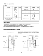
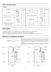
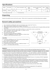
... FV-08WQ1 Part name Drawing Wall sleeve Screw I (4 x 30) Quantity Part name Screw III (4 x 8) 1 Template (Pattern paper) 4 Mounting plate Exterior hood 1 Screw II (4 x 6) (for safety. It also incorporates a thermal-cutoff device for new construction only) 2 Externsion sleeve Drawing Quantity 1 1 1 1 Description This Panasonic wall mounted ventilating fan uses a propeller fan driven by a capacitor motor. The grille is used. When the wall thickness is designed for extended service life with reduced energy consumption. List of wall...
... FV-08WQ1 Part name Drawing Wall sleeve Screw I (4 x 30) Quantity Part name Screw III (4 x 8) 1 Template (Pattern paper) 4 Mounting plate Exterior hood 1 Screw II (4 x 6) (for safety. It also incorporates a thermal-cutoff device for new construction only) 2 Externsion sleeve Drawing Quantity 1 1 1 1 Description This Panasonic wall mounted ventilating fan uses a propeller fan driven by a capacitor motor. The grille is used. When the wall thickness is designed for extended service life with reduced energy consumption. List of wall...
FV-08WQ1 Owner's Manual (English)
Page 3
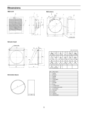
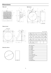
... 207 (9-7/16) (8-5/32) O 50 (31/32) U 127 (5) P 150 (5-29/32) Q 230 (9-1/16) R 240 (9-7/16) No. Part name 1 Grille 2 Frame 3 Blade 4 Motor 5 Connector 6 Hook 7 Flange 8 Duct 9 Junction box 10 Junction box cover 11 Connector 12 Shutter 13 Duct 14 Spring 15 Bird screen 3 hole Unit: mm (inch) A B C D E F 260 52 88 2 173ø 250 (10-1/4 ) (2-1/16) (3-15/32) (3/32) (6-13/16ø...
... 207 (9-7/16) (8-5/32) O 50 (31/32) U 127 (5) P 150 (5-29/32) Q 230 (9-1/16) R 240 (9-7/16) No. Part name 1 Grille 2 Frame 3 Blade 4 Motor 5 Connector 6 Hook 7 Flange 8 Duct 9 Junction box 10 Junction box cover 11 Connector 12 Shutter 13 Duct 14 Spring 15 Bird screen 3 hole Unit: mm (inch) A B C D E F 260 52 88 2 173ø 250 (10-1/4 ) (2-1/16) (3-15/32) (3/32) (6-13/16ø...
FV-08WQ1 Owner's Manual (English)
Page 4
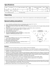
... applicable codes and standards, including fire-rated construction. To reduce the risk of fuel burning equipment to persons, observe the following; Sufficient air is to exhaust hazardous or explosive materials and vapors. 2. Do not use only. Installation work and electrical wiring must be done by the manufacturer. E. If this unit is needed for use in cooking area. (Fig. G.Before servicing or cleaning unit, switch power...
... applicable codes and standards, including fire-rated construction. To reduce the risk of fuel burning equipment to persons, observe the following; Sufficient air is to exhaust hazardous or explosive materials and vapors. 2. Do not use only. Installation work and electrical wiring must be done by the manufacturer. E. If this unit is needed for use in cooking area. (Fig. G.Before servicing or cleaning unit, switch power...
FV-08WQ1 Owner's Manual (English)
Page 5
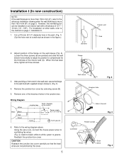
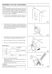
... the figure.). 2. green to a wall stud as shown in the wall. (Fig. 1) (Cut the hole next to greens. CAUTION: Reattach the junction box cover carefully so that the lead wires are not pinched by removing screw (B). 5. Installation I ). (Fig. 3) 4. Remove the junction box cover by the cover. 5 Wall sleeve A Fig. 2 13/m8"m Knockout hole B Hole in the junction box. Reattach the junction box cover. Wiring Diagram White Motor Black Red Green Junction box Switch (Available on page 2.
... the figure.). 2. green to a wall stud as shown in the wall. (Fig. 1) (Cut the hole next to greens. CAUTION: Reattach the junction box cover carefully so that the lead wires are not pinched by removing screw (B). 5. Installation I ). (Fig. 3) 4. Remove the junction box cover by the cover. 5 Wall sleeve A Fig. 2 13/m8"m Knockout hole B Hole in the junction box. Reattach the junction box cover. Wiring Diagram White Motor Black Red Green Junction box Switch (Available on page 2.
FV-08WQ1 Owner's Manual (English)
Page 6
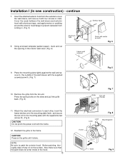
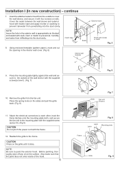
... the fan unit to the mounting plate with the supplied screw (screw III). (Fig 9) CAUTION: Do not pinch the power cord with mortar or caulk. Before painting, thoroughly wipe off any oil on the sides and pull the grille back. (Fig. 8) 11. continue 7. NOTE: Be sure to the frame. Remove the grille from coming in the interior wall cover. (Fig...
... the fan unit to the mounting plate with the supplied screw (screw III). (Fig 9) CAUTION: Do not pinch the power cord with mortar or caulk. Before painting, thoroughly wipe off any oil on the sides and pull the grille back. (Fig. 8) 11. continue 7. NOTE: Be sure to the frame. Remove the grille from coming in the interior wall cover. (Fig...
FV-08WQ1 Owner's Manual (English)
Page 7
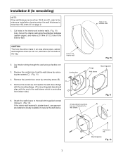
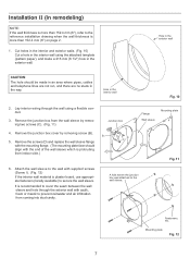
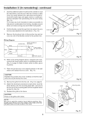
... wall Fig. 10 2. Hole in the exterior wall. Remove the junction box from indoor side.) Junction box B D C Flange Wall sleeve Mounting plate Fig. 11 6. Remove the junction box cover by removing two screws (C). (Fig. 11) 4. Hole in the exterior wall CAUTION: The hole should align with supplied screws (Screw I). (Fig. 12) If the interior wall material is protruding from the wall sleeve by removing screw (B). 5. A hole where the junction box was attached to the reference installation...
... wall Fig. 10 2. Hole in the exterior wall. Remove the junction box from indoor side.) Junction box B D C Flange Wall sleeve Mounting plate Fig. 11 6. Remove the junction box cover by removing two screws (C). (Fig. 11) 4. Hole in the exterior wall CAUTION: The hole should align with supplied screws (Screw I). (Fig. 12) If the interior wall material is protruding from the wall sleeve by removing screw (B). 5. A hole where the junction box was attached to the reference installation...

FV-08WQ1 Owner's Manual (English)
Page 8
... Motor Black Red Green Switch (Available on page 6) 13. white to paint the exterior hood. NOTE: Be sure to white; Flexible conduit Frame Latch Latch Fig. 14 Fig. 15 Mounting plate Grille Fig. 16 8 Remove the knockout hole in the junction box and secure one end of the hood. Refer to greens. 11. green to the wiring diagram above. Attach the electrical connectors...
... Motor Black Red Green Switch (Available on page 6) 13. white to paint the exterior hood. NOTE: Be sure to white; Flexible conduit Frame Latch Latch Fig. 14 Fig. 15 Mounting plate Grille Fig. 16 8 Remove the knockout hole in the junction box and secure one end of the hood. Refer to greens. 11. green to the wiring diagram above. Attach the electrical connectors...
FV-08WQ1 Owner's Manual (English)
Page 9
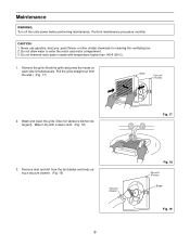
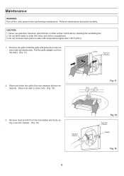
... to enter the motor and motor compartment. 3. Vacuum cleaner 9 Fig. 18 Fan unit (Frame) Blade Fig. 19 Maintenance WARNING: Turn off the units power before performing maintenance. CAUTION: 1. Remove the grille (Hold the grille and press the hooks on each side simultaneously. Remove dust and dirt from the wall.) (Fig. 17) Grille Fan unit (Frame) 2. Never use gasoline, benzene, paint...
... to enter the motor and motor compartment. 3. Vacuum cleaner 9 Fig. 18 Fan unit (Frame) Blade Fig. 19 Maintenance WARNING: Turn off the units power before performing maintenance. CAUTION: 1. Remove the grille (Hold the grille and press the hooks on each side simultaneously. Remove dust and dirt from the wall.) (Fig. 17) Grille Fan unit (Frame) 2. Never use gasoline, benzene, paint...
FV-08WQ1 Owner's Manual (English)
Page 10
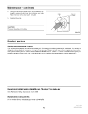
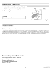
... and manufactured to locate the PASC Authorized Service Center nearest you.) PANASONIC HOME AND COMMERCIAL PRODUCTS COMPANY One Panasonic Way, Secaucus, NJ 07094 PANASONIC CANADA INC. 5770 Ambler Drive, Mississauga, Ontario L4W 2T3 10 Printed in Japan 08WQ14021D-I0298-4 Blade Fan unit (Frame) CAUTION: Press on the grille until it clicks. Reattach the grille. Using a cloth dampened with a clean cloth. (Fig...
... and manufactured to locate the PASC Authorized Service Center nearest you.) PANASONIC HOME AND COMMERCIAL PRODUCTS COMPANY One Panasonic Way, Secaucus, NJ 07094 PANASONIC CANADA INC. 5770 Ambler Drive, Mississauga, Ontario L4W 2T3 10 Printed in Japan 08WQ14021D-I0298-4 Blade Fan unit (Frame) CAUTION: Press on the grille until it clicks. Reattach the grille. Using a cloth dampened with a clean cloth. (Fig...
Installation Instructions
Page 1
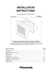
Table of Contents Pages List of components ...2 Description ...2 Reference installation drawing 2 Dimensions ...3 Specifications ...4 Unpacking ...4 General safety precautions 4 Installation I (In new construction 5-6 Installation II (In remodeling 7-8 Maintenance ...9-10 Product Service ...10 Failure to install, operate or service the Panasonic Ventilating Fan. Please retain for future reference. INSTALLATION INSTRUCTIONS Through the Wall Fan "Whisper Wall" Ventilating Fan FV-08WQ1 READ AND SAVE THESE INSTRUCTIONS Please read instructions carefully before attempting to ...
Table of Contents Pages List of components ...2 Description ...2 Reference installation drawing 2 Dimensions ...3 Specifications ...4 Unpacking ...4 General safety precautions 4 Installation I (In new construction 5-6 Installation II (In remodeling 7-8 Maintenance ...9-10 Product Service ...10 Failure to install, operate or service the Panasonic Ventilating Fan. Please retain for future reference. INSTALLATION INSTRUCTIONS Through the Wall Fan "Whisper Wall" Ventilating Fan FV-08WQ1 READ AND SAVE THESE INSTRUCTIONS Please read instructions carefully before attempting to ...
Installation Instructions
Page 2
... 254 mm (10"), mount the extension sleeve as shown below . When the wall thickness is easily detachable from the main unit. The motor is used. Exterior wall Flexible conduit Interior wall Junction box Exterior wall Flexible conduit Interior wall Junction box Connector Extension sleeve Connector Exterior hood Exterior hood Outdoor Wall sleeve Wall thickness Main unit Indoor Outdoor 2 Wall sleeve Wall thickness Main unit Indoor Reference installation drawing Wall thickness: 114.3 - 152...
... 254 mm (10"), mount the extension sleeve as shown below . When the wall thickness is easily detachable from the main unit. The motor is used. Exterior wall Flexible conduit Interior wall Junction box Exterior wall Flexible conduit Interior wall Junction box Connector Extension sleeve Connector Exterior hood Exterior hood Outdoor Wall sleeve Wall thickness Main unit Indoor Outdoor 2 Wall sleeve Wall thickness Main unit Indoor Reference installation drawing Wall thickness: 114.3 - 152...
Installation Instructions
Page 3
Part name 1 Grille 2 Frame 3 Blade 4 Motor 5 Connector 6 Hook 7 Flange 8 Duct 9 Junction box 10 Junction box cover 11 Connector 12 Shutter 13 Duct 14 Spring 15 Bird screen 3 Dimensions Main unit 5 Wall sleeve 1 2 9 11 7 8 3 10 4 6 D H E K F R A Exterior hood 4-5 dia. hole Unit: mm (inch) A B C D E F 260 52 88 2 173ø 250 (10-1/4 ) (2-1/16) (3-15/32) (3/32) (6-13/16ø) (9-27/32 ) G H I 4-5 dia. hole S Q Extension sleeve T B C 14 12 13...
Part name 1 Grille 2 Frame 3 Blade 4 Motor 5 Connector 6 Hook 7 Flange 8 Duct 9 Junction box 10 Junction box cover 11 Connector 12 Shutter 13 Duct 14 Spring 15 Bird screen 3 Dimensions Main unit 5 Wall sleeve 1 2 9 11 7 8 3 10 4 6 D H E K F R A Exterior hood 4-5 dia. hole Unit: mm (inch) A B C D E F 260 52 88 2 173ø 250 (10-1/4 ) (2-1/16) (3-15/32) (3/32) (6-13/16ø) (9-27/32 ) G H I 4-5 dia. hole S Q Extension sleeve T B C 14 12 13...
Installation Instructions
Page 4
... (CFM) 70 Noise Weight*2 lb. (kg) 1.1 3.1 (1.4) Unpack and carefully remove unit from a tub or shower. 4 C. H. Specifications Model Air direction V Hz Power consumption*1 (W) FV-08WQ1 Exhaust 120 60 17 *1 At 0.0" Static pressure, (Pa) *2 For main unit only. Installation Work And Electrical Wiring Must Be Done By Qualified Persons In Accordance With All Applicable Codes And Standards, Including Fire Rated Construction. Refer to list of fuel burning equipment to the outdoors. Follow...
... (CFM) 70 Noise Weight*2 lb. (kg) 1.1 3.1 (1.4) Unpack and carefully remove unit from a tub or shower. 4 C. H. Specifications Model Air direction V Hz Power consumption*1 (W) FV-08WQ1 Exhaust 120 60 17 *1 At 0.0" Static pressure, (Pa) *2 For main unit only. Installation Work And Electrical Wiring Must Be Done By Qualified Persons In Accordance With All Applicable Codes And Standards, Including Fire Rated Construction. Refer to list of fuel burning equipment to the outdoors. Follow...
Installation Instructions
Page 5
... box cover. white to greens. Installation I ). (Fig. 3) 4. Using the wire nuts, connect the house power wires to ventilating fan wires. (Fig. 4): black to the wiring diagram above. For installation on other walls, refer to the reference installation drawing when the wall thickness is more than 152.4 mm (6") on page 7, Installation II. 1. However, this has been done, tighten all three screws. Wiring Diagram White Motor Black Red Green Junction box Switch (Available on an interior wall with supplied screws (Screw I (In new...
... box cover. white to greens. Installation I ). (Fig. 3) 4. Using the wire nuts, connect the house power wires to ventilating fan wires. (Fig. 4): black to the wiring diagram above. For installation on other walls, refer to the reference installation drawing when the wall thickness is more than 152.4 mm (6") on page 7, Installation II. 1. However, this has been done, tighten all three screws. Wiring Diagram White Motor Black Red Green Junction box Switch (Available on an interior wall with supplied screws (Screw I (In new...
Installation Instructions
Page 6
... to the mounting plate with the supplied screw (screw III). (Fig 9) CAUTION: Do not pinch the power cord with the frame. 12. Attach the electrical connectors to each other, hook the frame latches onto the mounting plate latch, and secure the fan unit to prevent air, humidity and water from penetrating into the stud cavity. Cover the seam between the wall sleeve and...
... to the mounting plate with the supplied screw (screw III). (Fig 9) CAUTION: Do not pinch the power cord with the frame. 12. Attach the electrical connectors to each other, hook the frame latches onto the mounting plate latch, and secure the fan unit to prevent air, humidity and water from penetrating into the stud cavity. Cover the seam between the wall sleeve and...
Installation Instructions
Page 7
..., use appropriate fasteners (locally available) to prevent rainwater and air infiltration from indoor side.) Junction box B D C Flange Wall sleeve Mounting plate Fig. 11 6. Remove the junction box from the wall sleeve by removing screw (B). 5. Attach the wall sleeve to the wall with the end of the wall sleeve which is protruding from coming into stud cavity. Fasterners, etc. Hole in the way. Remove the junction box cover by removing...
..., use appropriate fasteners (locally available) to prevent rainwater and air infiltration from indoor side.) Junction box B D C Flange Wall sleeve Mounting plate Fig. 11 6. Remove the junction box from the wall sleeve by removing screw (B). 5. Attach the wall sleeve to the wall with the end of the wall sleeve which is protruding from coming into stud cavity. Fasterners, etc. Hole in the way. Remove the junction box cover by removing...
Installation Instructions
Page 8
.... 13 Wiring Diagram White Motor Black Red Green Switch (Available on the surface. NOTE: Be sure to the wall sleeve. (Fig. 14) 9. continued 7. Pull the flexible conduit through the hole where the junction box was attached to paint the exterior hood. Attach the electrical connectors to each other, hook the frame latches onto the mounting plate latch, and secure the fan unit to help prevent condensation...
.... 13 Wiring Diagram White Motor Black Red Green Switch (Available on the surface. NOTE: Be sure to the wall sleeve. (Fig. 14) 9. continued 7. Pull the flexible conduit through the hole where the junction box was attached to paint the exterior hood. Attach the electrical connectors to each other, hook the frame latches onto the mounting plate latch, and secure the fan unit to help prevent condensation...
Installation Instructions
Page 9
... water to enter the motor and motor compartment. 3. Pull the grille straight out from the fan blades and body using a vacuum cleaner. (Fig. 19) . Wipe it dry with temperature higher than 140oF (60oC). 1. Wash and clean the grille (Use non-abrasive kitchen detergent). Vacuum cleaner 9 Fig. 18 Fan unit (Frame) Blade Fig. 19 Perform maintenance procedure monthly. Remove the grille (Hold...
... water to enter the motor and motor compartment. 3. Pull the grille straight out from the fan blades and body using a vacuum cleaner. (Fig. 19) . Wipe it dry with temperature higher than 140oF (60oC). 1. Wash and clean the grille (Use non-abrasive kitchen detergent). Vacuum cleaner 9 Fig. 18 Fan unit (Frame) Blade Fig. 19 Perform maintenance procedure monthly. Remove the grille (Hold...
Installation Instructions
Page 10
... dry with a non-abrasive kitchen detergent, remove any dirt from the fan blades and body. Maintenance - No service information is maintained to support your product's warranty. (In the U.S.A., call 1-800-545-2672 to ensure a minimum of covers. Your product is designed and manufactured to locate the PASC Authorized Service Center nearest you.) Panasonic Corporation of North America Two Riverfront...
... dry with a non-abrasive kitchen detergent, remove any dirt from the fan blades and body. Maintenance - No service information is maintained to support your product's warranty. (In the U.S.A., call 1-800-545-2672 to ensure a minimum of covers. Your product is designed and manufactured to locate the PASC Authorized Service Center nearest you.) Panasonic Corporation of North America Two Riverfront...


