Service Manual
Page 7
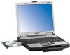
... the model number: Check the bottom of the computer or the box the computer came in at the time of purchase. CF-74CCBAXBM / CF-74CCBADBM CPU Intel® Core™ Duo Processor T2400 (1.83 GHz, 2 MB*1 L2 cache, 667 MHz FSB) Chipset Intel® 945GM Memory*1 512 MB (1536 MB Max.) Video Memory*1*2 UMA (128 MB Max.) Hard Disk Drive*3 Approx. 80 GB CD/DVD Drive DVD-ROM...
... the model number: Check the bottom of the computer or the box the computer came in at the time of purchase. CF-74CCBAXBM / CF-74CCBADBM CPU Intel® Core™ Duo Processor T2400 (1.83 GHz, 2 MB*1 L2 cache, 667 MHz FSB) Chipset Intel® 945GM Memory*1 512 MB (1536 MB Max.) Video Memory*1*2 UMA (128 MB Max.) Hard Disk Drive*3 Approx. 80 GB CD/DVD Drive DVD-ROM...

Service Manual
Page 8
... to use a card that supports the higher transfer rate. *16 Only for Panasonic SD Memory Cards with the LAN Power-saving function's Auto-off setting set by the user. *3 1GB = 1,000,000,000 bytes. The size of the Video Memory cannot be used. *9 A 16,777,216 color display is achieved by TOSHIBA*12, Wireless Switch Utility, Hotkey Settings, Battery Recalibration, LAN Power-Saving Utility, Infineon TPM Professional Package*24 Setup Utility, Hard Disk Backup Utility*25, Hard Disk Data Erase Utility*25 Wireless LAN Intel PRO / Wireless 3945...
... to use a card that supports the higher transfer rate. *16 Only for Panasonic SD Memory Cards with the LAN Power-saving function's Auto-off setting set by the user. *3 1GB = 1,000,000,000 bytes. The size of the Video Memory cannot be used. *9 A 16,777,216 color display is achieved by TOSHIBA*12, Wireless Switch Utility, Hotkey Settings, Battery Recalibration, LAN Power-Saving Utility, Infineon TPM Professional Package*24 Setup Utility, Hard Disk Backup Utility*25, Hard Disk Data Erase Utility*25 Wireless LAN Intel PRO / Wireless 3945...

Service Manual
Page 9
... status (Off: Power off/Hibernation, Green: Power on, Blinking green: Standby, Blinking green rapidly: Cannot power on or resume due to the speakers. 2-1 Q :Wireless switch CAUTION Do not put a metallic object or magnetic media close to low temperature.) : Battery status J : Power button K :Function key F : Carrying handle G :Wireless LAN antenna H :LCD I : LED indicator : Caps lock : Numeric key (NumLk) : Scroll lock (ScrLk) : Multimedia pocket device status or the second battery status : Hard disk drive status M :Keyboard N :Touch pad O :Microphone jack You can connect headphones or...
... status (Off: Power off/Hibernation, Green: Power on, Blinking green: Standby, Blinking green rapidly: Cannot power on or resume due to the speakers. 2-1 Q :Wireless switch CAUTION Do not put a metallic object or magnetic media close to low temperature.) : Battery status J : Power button K :Function key F : Carrying handle G :Wireless LAN antenna H :LCD I : LED indicator : Caps lock : Numeric key (NumLk) : Scroll lock (ScrLk) : Multimedia pocket device status or the second battery status : Hard disk drive status M :Keyboard N :Touch pad O :Microphone jack You can connect headphones or...
Service Manual
Page 10
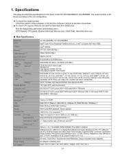
...Refer to the instruction manual of the cable. Right side Rear side EX PC Bottom A :ExpressCard slot K :LAN port B :PC Card slot L : Modem port C :Smart Card slot M :Serial port N :External display port D :USB port E : SD Memory Card slot F : Expansion bus connector O :Security lock You can connect a Kensington cable. P : Battery pack Q :Battery latch R :Multimedia pocket release button G :SD Memory Card indicator (Blinking: During access or a password is requested) H :Ventilation hole I : Stylus holder J : DC-IN jack S : Hard disk drive latch T : RAM module slot CAUTION Do not...
...Refer to the instruction manual of the cable. Right side Rear side EX PC Bottom A :ExpressCard slot K :LAN port B :PC Card slot L : Modem port C :Smart Card slot M :Serial port N :External display port D :USB port E : SD Memory Card slot F : Expansion bus connector O :Security lock You can connect a Kensington cable. P : Battery pack Q :Battery latch R :Multimedia pocket release button G :SD Memory Card indicator (Blinking: During access or a password is requested) H :Ventilation hole I : Stylus holder J : DC-IN jack S : Hard disk drive latch T : RAM module slot CAUTION Do not...

Service Manual
Page 11
... Express Card GBE antenna Wireless LAN Golan 11ABG PM Signals SO-DIMM Main Memory DDR2 SDRAM SO-DIMM Extension Memory DDR2 SDRAM 3.3V 32bit PCI Bus 33MHz PCMCIA R5C811A/812A SD Card Smart Card TYPE II RJ11 Data Modem Agere or Conexant MDC1.5 I/F Speaker AMP Speaker Sound STAC9200 Beep ODD Bluetooth Touch screen Wide Range Wireless BIOS SPI 8Mbit 25LF080 CRT Buffer CRT Serial Super I /O Board
... Express Card GBE antenna Wireless LAN Golan 11ABG PM Signals SO-DIMM Main Memory DDR2 SDRAM SO-DIMM Extension Memory DDR2 SDRAM 3.3V 32bit PCI Bus 33MHz PCMCIA R5C811A/812A SD Card Smart Card TYPE II RJ11 Data Modem Agere or Conexant MDC1.5 I/F Speaker AMP Speaker Sound STAC9200 Beep ODD Bluetooth Touch screen Wide Range Wireless BIOS SPI 8Mbit 25LF080 CRT Buffer CRT Serial Super I /O Board
Service Manual
Page 13
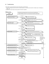
... Replace LCD back light. Replace inverter board. Replace main board (Check fuse at power source). Set-up utility starting Not displayed properly on screen', etc. Replace if defective. Heavy trouble e.g., 'Set cannot be defective. Since flaws may appear on specific media, DVD or CD media can be turned ON', 'Set fails to start ', 'No display on screen. Each kind of trouble in use. Know-how of diagnosis upon occurrence of K/B connector in operation. Main board check NG Replace main board OK Make...
... Replace LCD back light. Replace inverter board. Replace main board (Check fuse at power source). Set-up utility starting Not displayed properly on screen', etc. Replace if defective. Heavy trouble e.g., 'Set cannot be defective. Since flaws may appear on specific media, DVD or CD media can be turned ON', 'Set fails to start ', 'No display on screen. Each kind of trouble in use. Know-how of diagnosis upon occurrence of K/B connector in operation. Main board check NG Replace main board OK Make...
Service Manual
Page 15
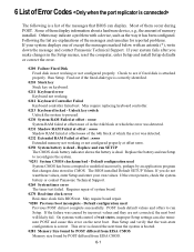
... successfully. Others may indicate a problem with an asterisk (*), write down the message and contact Panasonic Technical Support. The BIOS installed Default SETUP Values. May require board repair. *0280 Previous boot incomplete - On systems with control of wait states, improper Setup settings can display. 6 List of Error Codes The following is a list of the messages that BIOS can also terminate POST and cause this error on keyboard. 0211 Keyboard error Keyboard not working or not configured properly. If...
... successfully. Others may indicate a problem with an asterisk (*), write down the message and contact Panasonic Technical Support. The BIOS installed Default SETUP Values. May require board repair. *0280 Previous boot incomplete - On systems with control of wait states, improper Setup settings can display. 6 List of Error Codes The following is a list of the messages that BIOS can also terminate POST and cause this error on keyboard. 0211 Keyboard error Keyboard not working or not configured properly. If...
Service Manual
Page 16
... Configuration Data Problem with NVRAM (CMOS) data. Enter Setup and see if fixed disk and drive A: are properly identified. Parity Check 2 nnnn Parity error found Operating system cannot be located on the screen. BIOS attempts to locate the address and display it displays ????. Write down and follow the information shown on the screen. 02D0 System cache error - Cache disabled Contact Panasonic Technical Support. 02F0: CPU ID: CPU socket number for Multi-Processor error. 02F4: EISA CMOS...
... Configuration Data Problem with NVRAM (CMOS) data. Enter Setup and see if fixed disk and drive A: are properly identified. Parity Check 2 nnnn Parity error found Operating system cannot be located on the screen. BIOS attempts to locate the address and display it displays ????. Write down and follow the information shown on the screen. 02D0 System cache error - Cache disabled Contact Panasonic Technical Support. 02F0: CPU ID: CPU socket number for Multi-Processor error. 02F4: EISA CMOS...
Service Manual
Page 17
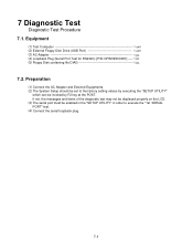
... be set to execute the "1st SERIAL PORT" test. (4) Connect the serial loopback plug. 7-1 If not, the messages and items of the diagnostic test may not be displayed properly on the LCD. (3) The serial port must be enabled in the "SETUP UTILITY" in order to the factory setting values by F2 key at the POST. Equipment (1) Test Computer 1 unit (2) External Floppy Disk Drive (USB Port 1 unit (3) AC Adapter 1 pc. (4) Loopback Plug (Serial Port Test...
... be set to execute the "1st SERIAL PORT" test. (4) Connect the serial loopback plug. 7-1 If not, the messages and items of the diagnostic test may not be displayed properly on the LCD. (3) The serial port must be enabled in the "SETUP UTILITY" in order to the factory setting values by F2 key at the POST. Equipment (1) Test Computer 1 unit (2) External Floppy Disk Drive (USB Port 1 unit (3) AC Adapter 1 pc. (4) Loopback Plug (Serial Port Test...
Service Manual
Page 18
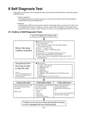
... & Exit" and press Enter. Quit Select please [ 1, 2, 3, 4, 5, 6, Q ] ? Choose Yes for "Load default Configuration now?" DIAG on the power. LAN test 4. Important notice 1. 8 Self Diagnosis Test Floppy disk is turned on, the self-diagnostics tests will not work. 8.1. Starting up the setup utility Turn on FD (CF-74) 2. Wireless LAN test (Wireless LAN AB G Model only) Q. DIAG on FD The parallel port and CD-ROM drive can be sure to enter setup" appears on the...
... & Exit" and press Enter. Quit Select please [ 1, 2, 3, 4, 5, 6, Q ] ? Choose Yes for "Load default Configuration now?" DIAG on the power. LAN test 4. Important notice 1. 8 Self Diagnosis Test Floppy disk is turned on, the self-diagnostics tests will not work. 8.1. Starting up the setup utility Turn on FD (CF-74) 2. Wireless LAN test (Wireless LAN AB G Model only) Q. DIAG on FD The parallel port and CD-ROM drive can be sure to enter setup" appears on the...
Service Manual
Page 19
.../2 MOUSE REG 19 COMMUNICATION SERIAL WRAP TEST 20 SERIAL ALL INTERNAL TEST 21 PARALLEL REGISTER R/W 22 AUX 23 (Auxiliary functions) PCIC ALL TEST Card Bus Reg 24 USB Reg 25 VIDEO 26 (Display related) VGA ALL TEST SVGA RAM TEST 27 DISK 28 (FDD, HDD) FD WT/RD/WP TEST HDD ALL TEST 29 UNIQUE 30 (Individual functions) ECP REGISTER R/W EPP REGISTER R/W 31 EXT. 8.1.1 List...
.../2 MOUSE REG 19 COMMUNICATION SERIAL WRAP TEST 20 SERIAL ALL INTERNAL TEST 21 PARALLEL REGISTER R/W 22 AUX 23 (Auxiliary functions) PCIC ALL TEST Card Bus Reg 24 USB Reg 25 VIDEO 26 (Display related) VGA ALL TEST SVGA RAM TEST 27 DISK 28 (FDD, HDD) FD WT/RD/WP TEST HDD ALL TEST 29 UNIQUE 30 (Individual functions) ECP REGISTER R/W EPP REGISTER R/W 31 EXT. 8.1.1 List...
Service Manual
Page 20
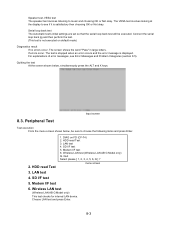
... settings are set so that the serial loop back test will be sure to choose the following items and press Enter. 2. Connect the serial loop back jig and then perform the test. (This test is not executed on FD (CF-74) 2. HDD read Test 3. Modem I /F test 5. Wireless LAN test (Wireless LAN AB G Model only) This test checks for internal LAN device. Choose LAN test and press Enter. 8-3 If errors occur...
... settings are set so that the serial loop back test will be sure to choose the following items and press Enter. 2. Connect the serial loop back jig and then perform the test. (This test is not executed on FD (CF-74) 2. HDD read Test 3. Modem I /F test 5. Wireless LAN test (Wireless LAN AB G Model only) This test checks for internal LAN device. Choose LAN test and press Enter. 8-3 If errors occur...

Service Manual
Page 23
... SERIAL WRAP TEST 19 SERIAL ALL INTERNAL TEST 20 PARALLEL REGISTER R/W AUX PCIC ALL TEST 21 (Auxiliary functions) Card Bus REG USB REG 22 VIDEO VGA ALL TEST 23 (Display related) SVGA RAM TEST 24 VESA MODE TEST 25 DISK FD WT/RD/WP TEST 26 (FDD, HDD) HDD ALL TEST 27 UNIQUE ECP REGISTER R/W 28 (Individual functions) EPP REGISTER R/W 29 EXT. Error Messages and Troubleshooting...
... SERIAL WRAP TEST 19 SERIAL ALL INTERNAL TEST 20 PARALLEL REGISTER R/W AUX PCIC ALL TEST 21 (Auxiliary functions) Card Bus REG USB REG 22 VIDEO VGA ALL TEST 23 (Display related) SVGA RAM TEST 24 VESA MODE TEST 25 DISK FD WT/RD/WP TEST 26 (FDD, HDD) HDD ALL TEST 27 UNIQUE ECP REGISTER R/W 28 (Individual functions) EPP REGISTER R/W 29 EXT. Error Messages and Troubleshooting...

Service Manual
Page 24
... MODEM JACK USB CN16 ANTENNA PCB L CN28 MAIN PCB CN5 CN25 CN4 DIMM MEMORY CARD CN8 CN2 CN3 SPEAKER (L) CN1002 USB PCB CN1701 USB CN1702 DC-IN JK1501 CN1501 DC-IN PCB DVD-ROM DRIVE FAN MOTOR LITHIUM BATTERY WIRELESS MODULE ANTENNA PCB R JK2 JK1 Headphone Microphone KBD FPC KEYBOARD PCMCIA SLOT CN26 CN13 HDD PACK CN1301 SW1304 SW1301 Connector by Cable Direct connection by Connectors Parts on Bottom Side PAD...
... MODEM JACK USB CN16 ANTENNA PCB L CN28 MAIN PCB CN5 CN25 CN4 DIMM MEMORY CARD CN8 CN2 CN3 SPEAKER (L) CN1002 USB PCB CN1701 USB CN1702 DC-IN JK1501 CN1501 DC-IN PCB DVD-ROM DRIVE FAN MOTOR LITHIUM BATTERY WIRELESS MODULE ANTENNA PCB R JK2 JK1 Headphone Microphone KBD FPC KEYBOARD PCMCIA SLOT CN26 CN13 HDD PACK CN1301 SW1304 SW1301 Connector by Cable Direct connection by Connectors Parts on Bottom Side PAD...

Service Manual
Page 25
... Hook HDD HDD FPC HDD Latch Knob HDD Unit Latch 2 Latch 1 Battery Pack 6 4 5 7 MP Latch 1 2 3 DVD-ROM Drive Unit Battery Pack 1. Push the MP Latch (6), and then without releasing it , slide and remove the HDD Unit. (5) DVD-ROM Drive Unit 1. 10 Disassembly/Reassembly Note: Power off the power. • Disconnect the AC adaptor. • Remove the optional DIMM memory card and PCMCIA card if they are connected. • Remove other devices if they are connected. Disassembly Instructions 10.1.1. Use new parts...
... Hook HDD HDD FPC HDD Latch Knob HDD Unit Latch 2 Latch 1 Battery Pack 6 4 5 7 MP Latch 1 2 3 DVD-ROM Drive Unit Battery Pack 1. Push the MP Latch (6), and then without releasing it , slide and remove the HDD Unit. (5) DVD-ROM Drive Unit 1. 10 Disassembly/Reassembly Note: Power off the power. • Disconnect the AC adaptor. • Remove the optional DIMM memory card and PCMCIA card if they are connected. • Remove other devices if they are connected. Disassembly Instructions 10.1.1. Use new parts...

Service Manual
Page 33
...surplus length under the LCD. n Arranging the TP Power Cable and Attaching the TP/LCD Sheet Ensure the Tape does not cover the Connecter port. Safety Working Safety Working 0~2mm 0~2mm Tape Fold it from the Inverter Case. AB Safety Working Arrange the Cable A and B coming out of the Connecter. Fix the Connector of the...the Inverter Cable using the Tape. Avoid any kink, twist or stress on the two-sided tapes. Do not reuse the Inverter once you removed it back and attach to the mark. Pass the Cable between the LCD and the Inverter Case. Safety Working Ensure the Cables do ...
...surplus length under the LCD. n Arranging the TP Power Cable and Attaching the TP/LCD Sheet Ensure the Tape does not cover the Connecter port. Safety Working Safety Working 0~2mm 0~2mm Tape Fold it from the Inverter Case. AB Safety Working Arrange the Cable A and B coming out of the Connecter. Fix the Connector of the...the Inverter Cable using the Tape. Avoid any kink, twist or stress on the two-sided tapes. Do not reuse the Inverter once you removed it back and attach to the mark. Pass the Cable between the LCD and the Inverter Case. Safety Working Ensure the Cables do ...

Service Manual
Page 50
..., IO PCB, LED PCB, USB PCB, DC-IN PCB, TS PCB, SD PCB, PAD SWITCH DIMM MODEM WIRELESS LAN MODULE CABLE MODEM ASSY LITHIUM BATTERY PCB, W-LAN ANTENNA L CABLE, ANTENNA L (Black) PCB, W-LAN ANTENNA R CABLE, ANTENNA R (Gray) HDD MOUNTING KIT FPC, HDD HDD CASE UPPER HDD DAMPER HDD CASE HOLDER HDD CN HDD FPC, KBD DRAIVE, DVD-ROM & CD-R/RW BEZEL ASSY FPC, MP DRIVE LCD UNIT ASS'Y LCD UNIT LCD DAMPER A LCD DAMPER B LCD DAMPER C LCD DAMPER D TOUCH SCREEN PANEL KIT TS...
..., IO PCB, LED PCB, USB PCB, DC-IN PCB, TS PCB, SD PCB, PAD SWITCH DIMM MODEM WIRELESS LAN MODULE CABLE MODEM ASSY LITHIUM BATTERY PCB, W-LAN ANTENNA L CABLE, ANTENNA L (Black) PCB, W-LAN ANTENNA R CABLE, ANTENNA R (Gray) HDD MOUNTING KIT FPC, HDD HDD CASE UPPER HDD DAMPER HDD CASE HOLDER HDD CN HDD FPC, KBD DRAIVE, DVD-ROM & CD-R/RW BEZEL ASSY FPC, MP DRIVE LCD UNIT ASS'Y LCD UNIT LCD DAMPER A LCD DAMPER B LCD DAMPER C LCD DAMPER D TOUCH SCREEN PANEL KIT TS...

Use and Care Guide
Page 10
... is powered off before you hear an audible click. B • NEVER REMOVE THE HARD DISK DRIVE PACK WHEN THE UNIT IS IN SUSPEND OR HIBERNATION MODE • THE HARD DISK DRIVE PACK IS KEYED AND WILL ONLY SEAT PROPERLY IN ONE ORIENTATION. Make certain to flip the hard disk drive so that the laptop is closest to the left (towards the right 3. Insert the hard disk drive pack...
... is powered off before you hear an audible click. B • NEVER REMOVE THE HARD DISK DRIVE PACK WHEN THE UNIT IS IN SUSPEND OR HIBERNATION MODE • THE HARD DISK DRIVE PACK IS KEYED AND WILL ONLY SEAT PROPERLY IN ONE ORIENTATION. Make certain to flip the hard disk drive so that the laptop is closest to the left (towards the right 3. Insert the hard disk drive pack...

Use and Care Guide
Page 23
Troubleshooting Diagnostic Utility • Start / Restart the device • At the Panasonic welcome screen, press the following order: • AC Adapter must be attached to the system • Total run time for all diagnostics can take up to 22 minutes • Typical run time is a BIOS password, you can use the [CTRL]+[F10] key combination to 15-20 minutes with no errors 23 This...
Troubleshooting Diagnostic Utility • Start / Restart the device • At the Panasonic welcome screen, press the following order: • AC Adapter must be attached to the system • Total run time for all diagnostics can take up to 22 minutes • Typical run time is a BIOS password, you can use the [CTRL]+[F10] key combination to 15-20 minutes with no errors 23 This...

Use and Care Guide
Page 24
Troubleshooting Diagnostic Utility • Total run time for all diagnostics can take up to 22 minutes • Typical run time is closer to 15-20 minutes with no errors • Flashes yell and blue when testing 24 • CPU/System • RAM (installed RAM size will display) • HDD (installed HDD size will display) • Video • Sound • Modem • LAN • Wireless LAN • Bluetooth • USB • PC Card • Modem • Keyboard • Touch Pad • Touch Screen
Troubleshooting Diagnostic Utility • Total run time for all diagnostics can take up to 22 minutes • Typical run time is closer to 15-20 minutes with no errors • Flashes yell and blue when testing 24 • CPU/System • RAM (installed RAM size will display) • HDD (installed HDD size will display) • Video • Sound • Modem • LAN • Wireless LAN • Bluetooth • USB • PC Card • Modem • Keyboard • Touch Pad • Touch Screen


