
Service Manual
Page 30
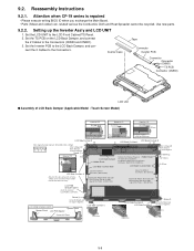
...Damper, and con- Set the Inverter PCB to the LCD Front Cabinet/TS Panel. 2. nect the 2 Cables to the LCD Frame. Screw Detail of the Frame. (0 to the right edge of "A" A 0 3mm LCD Back Damper Holder Sheet LCD Back Cushion Side LCD Back Cushion ... Unit n Assembly of LCD Back Damper (Applicable Model : Touch Screen Model) Detail of "B" 0 1mm Detail of "C" 0 1mm Detail of "D" 0 1mm 0 0.5mm Pass the Cable 0 0.5mm under the protrusion. 9.2. Reassembly Instructions 9.2.1. Attention when CF-19 series is repaired • Please execute writing BIOS ID when you exchange the ...
...Damper, and con- Set the Inverter PCB to the LCD Front Cabinet/TS Panel. 2. nect the 2 Cables to the LCD Frame. Screw Detail of the Frame. (0 to the right edge of "A" A 0 3mm LCD Back Damper Holder Sheet LCD Back Cushion Side LCD Back Cushion ... Unit n Assembly of LCD Back Damper (Applicable Model : Touch Screen Model) Detail of "B" 0 1mm Detail of "C" 0 1mm Detail of "D" 0 1mm 0 0.5mm Pass the Cable 0 0.5mm under the protrusion. 9.2. Reassembly Instructions 9.2.1. Attention when CF-19 series is repaired • Please execute writing BIOS ID when you exchange the ...
Service Manual
Page 32
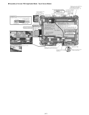
... Cabinet.) Cushion High TS PWB LCD Side Cushion F Voltage Label Connect Insert it between the ribs. (Fit to the Cabinet.) 0 3mm Inverter Ass'y Details of Cable Avoid running over the end of steel plate by 1 to the Tape left and right Connectors. Attach the Inverter Ass'y in the Avoid...is front. Wrap of the LCD Module because the line comes off. Hold the Connector part when connecting/disconnecting. Safety Working 0 1mm LCD Ass'y Details of "A" Ensure the edge of right and left. Note for attaching Conductive Tape Conductive Tape Wind round the LCD Cable a few times and attach ...
... Cabinet.) Cushion High TS PWB LCD Side Cushion F Voltage Label Connect Insert it between the ribs. (Fit to the Cabinet.) 0 3mm Inverter Ass'y Details of Cable Avoid running over the end of steel plate by 1 to the Tape left and right Connectors. Attach the Inverter Ass'y in the Avoid...is front. Wrap of the LCD Module because the line comes off. Hold the Connector part when connecting/disconnecting. Safety Working 0 1mm LCD Ass'y Details of "A" Ensure the edge of right and left. Note for attaching Conductive Tape Conductive Tape Wind round the LCD Cable a few times and attach ...
Service Manual
Page 33
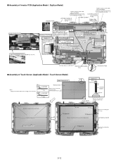
... Spacer A 0 1mm Match to the marking line. 0.5 mm 9-12 NG Laminate T/S Laminate Protect Sheet Attach it to the front side. (Using the jig) Dimensional tolerance: 0.2 T/S A Details of "A" Back Side 6 0.5mm TS FPC Spacer 0 0.5mm Touch Screen TS Spacer A Match to the wall of Touch Screen (Applicable Model : Touch Screen Model) Touch...
... Spacer A 0 1mm Match to the marking line. 0.5 mm 9-12 NG Laminate T/S Laminate Protect Sheet Attach it to the front side. (Using the jig) Dimensional tolerance: 0.2 T/S A Details of "A" Back Side 6 0.5mm TS FPC Spacer 0 0.5mm Touch Screen TS Spacer A Match to the wall of Touch Screen (Applicable Model : Touch Screen Model) Touch...
Service Manual
Page 35
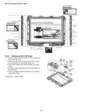
.... C D Match to the edge of Cabinet B Screw LAN Main /BT ANT Screw Match to the edge of Cabinet Screw EVDO-AUX Screw Match to front 3. Details of "D" Insert it between the wall and the rib after attaching. Wind the Cable coming out of Cabinet A Cable Cushion Attachment Method (3 Places) Bundle and...and the 2 Cable Holder Plates. Note: Avoid any stress on each hook Screw LAN-AUX ANT Screw Match to the edge of Cabinet Safety Working Details of "D" Match to the edge of the LCD Unit counterclockwise to the LCD Hinge. 2. n Line Processing of Antenna Cable Safety Working...
.... C D Match to the edge of Cabinet B Screw LAN Main /BT ANT Screw Match to the edge of Cabinet Screw EVDO-AUX Screw Match to front 3. Details of "D" Insert it between the wall and the rib after attaching. Wind the Cable coming out of Cabinet A Cable Cushion Attachment Method (3 Places) Bundle and...and the 2 Cable Holder Plates. Note: Avoid any stress on each hook Screw LAN-AUX ANT Screw Match to the edge of Cabinet Safety Working Details of "D" Match to the edge of the LCD Unit counterclockwise to the LCD Hinge. 2. n Line Processing of Antenna Cable Safety Working...
Service Manual
Page 41
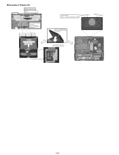
Insert all of antenna cables into the notch of "A" Safety Working Note Avoid any stress on the Top Case, and then fold back. n Assembly of Display Unit Details of the board. 9-20 Pass the Cable through the groove. Black/White Blue/Gray Brown LCD UNIT Set to the Top Case Assy A LCD Cable Insert Position Order of fixing Screw Screw Screw Screw Screw Screw Screw Screw Close the LCD hooking the Hinge on the Cable. Note: Running over affects the waterproof performance..
Insert all of antenna cables into the notch of "A" Safety Working Note Avoid any stress on the Top Case, and then fold back. n Assembly of Display Unit Details of the board. 9-20 Pass the Cable through the groove. Black/White Blue/Gray Brown LCD UNIT Set to the Top Case Assy A LCD Cable Insert Position Order of fixing Screw Screw Screw Screw Screw Screw Screw Screw Close the LCD hooking the Hinge on the Cable. Note: Running over affects the waterproof performance..
Service Manual
Page 50
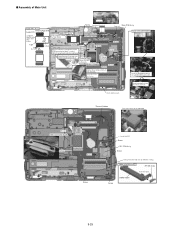
... then lock. DIMM HOLDER Ass'y RF SW Knob Insert the hook DIMM Holder 9-29 Screw (Note for spraying around when applying.) Connect Main PCB Ass'y Details of the FPC. 3mm Audio FPC Ass'y Insert it on the HDD Connector for Safety Insert the Bastaraid between the LAN/MODEM Connectors. Thermal Sheet...
... then lock. DIMM HOLDER Ass'y RF SW Knob Insert the hook DIMM Holder 9-29 Screw (Note for spraying around when applying.) Connect Main PCB Ass'y Details of the FPC. 3mm Audio FPC Ass'y Insert it on the HDD Connector for Safety Insert the Bastaraid between the LAN/MODEM Connectors. Thermal Sheet...
Service Manual
Page 60
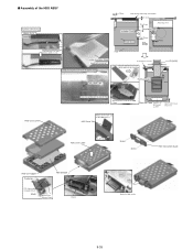
Attach it Make the Hook inside of 1 Details for attachment of the HDD. 3mm Revision Label Matches to the center 2mm Match to the level. 0 to 0.5 mm. n Assembly of the HDD ASSY Safety ...
Attach it Make the Hook inside of 1 Details for attachment of the HDD. 3mm Revision Label Matches to the center 2mm Match to the level. 0 to 0.5 mm. n Assembly of the HDD ASSY Safety ...