
BTLH80W User Guide
Page 2
... FIRE OR SHOCK HAZARD, KEEP THIS EQUIPMENT AWAY FROM ALL LIQUIDS. This equipment generates, uses, and can radiate radio frequency energy, and if not installed and used in your local authorities, or the Electronics Industries Alliance: CAUTION: In order to the floor so that contains mercury. Operation of important operating and maintenance (service) instructions in a residential area...
... FIRE OR SHOCK HAZARD, KEEP THIS EQUIPMENT AWAY FROM ALL LIQUIDS. This equipment generates, uses, and can radiate radio frequency energy, and if not installed and used in your local authorities, or the Electronics Industries Alliance: CAUTION: In order to the floor so that contains mercury. Operation of important operating and maintenance (service) instructions in a residential area...
BTLH80W User Guide
Page 3
...servicing to be used for the main power source in this first! (For BT-LH80WE) DO NOT REMOVE PANEL COVERS BY UNSCREWING THEM. WARNING: • TO REDUCE THE RISK OF FIRE OR SHOCK HAZARD, DO NOT EXPOSE THIS EQUIPMENT TO RAIN OR MOISTURE. • TO REDUCE THE RISK OF FIRE OR SHOCK HAZARD, KEEP ...to maintain adequate ventilation, do not obstruct the ventilation. No user serviceable parts inside the rack to between 5 °C to 40 °C. • Bolt the rack securely to the floor so that curtains and any other materials do not install or place this unit in a bookcase, built-in as ...
...servicing to be used for the main power source in this first! (For BT-LH80WE) DO NOT REMOVE PANEL COVERS BY UNSCREWING THEM. WARNING: • TO REDUCE THE RISK OF FIRE OR SHOCK HAZARD, DO NOT EXPOSE THIS EQUIPMENT TO RAIN OR MOISTURE. • TO REDUCE THE RISK OF FIRE OR SHOCK HAZARD, KEEP ...to maintain adequate ventilation, do not obstruct the ventilation. No user serviceable parts inside the rack to between 5 °C to 40 °C. • Bolt the rack securely to the floor so that curtains and any other materials do not install or place this unit in a bookcase, built-in as ...

BTLH80W User Guide
Page 4
... Picture adjusting knob status 12 Sharpness display 13 Function display 13 DC power supply voltage and battery level display 13 Menu display 13 Menu operations 14 User Data 15 Saving user data 15 Loading user data 15 Main Menu 16 Menu configuration 16 MARKER 17 Types of MARKER 18 VIDEO CONFIG 19 SYSTEM CONFIG 21 VF CONFIG 22 FUNCTION 23 GPI 28 INPUT SELECT 29 CONTROL 30 HOURMETER 30 REMOTE Specifications...
... Picture adjusting knob status 12 Sharpness display 13 Function display 13 DC power supply voltage and battery level display 13 Menu display 13 Menu operations 14 User Data 15 Saving user data 15 Loading user data 15 Main Menu 16 Menu configuration 16 MARKER 17 Types of MARKER 18 VIDEO CONFIG 19 SYSTEM CONFIG 21 VF CONFIG 22 FUNCTION 23 GPI 28 INPUT SELECT 29 CONTROL 30 HOURMETER 30 REMOTE Specifications...
BTLH80W User Guide
Page 6
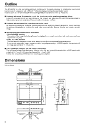
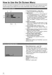
... interlace signals to -understand red, making camera focus adjustments very easy. • PIXEL TO PIXEL function The input signal is displayed without generating time delays per field. New functions that support focus adjustments • FOCUS-IN-RED function The section of an image approximately 19 inches wide. If you are not resizing the image, you can be used as a VF (viewfinder) for broadcasting service and business use. It is compatible...
... interlace signals to -understand red, making camera focus adjustments very easy. • PIXEL TO PIXEL function The input signal is displayed without generating time delays per field. New functions that support focus adjustments • FOCUS-IN-RED function The section of an image approximately 19 inches wide. If you are not resizing the image, you can be used as a VF (viewfinder) for broadcasting service and business use. It is compatible...

BTLH80W User Guide
Page 7
... the button is pressed, the input changes in the following order: YPBPR → VF-YPBPR/VF-VIDEO → VIDEO → SDI. YPBPR : Analog component input VF-YPBPR / VF-VIDEO∗1 : Viewfinder input VIDEO SDI∗2 : Video input : Serial digital interface input (compatible with HD/SD) • The input line when the power supply is switched ON is the one that are saved by a control signal from the factory preset values, the LEDs to skip input lines...
... the button is pressed, the input changes in the following order: YPBPR → VF-YPBPR/VF-VIDEO → VIDEO → SDI. YPBPR : Analog component input VF-YPBPR / VF-VIDEO∗1 : Viewfinder input VIDEO SDI∗2 : Video input : Serial digital interface input (compatible with HD/SD) • The input line when the power supply is switched ON is the one that are saved by a control signal from the factory preset values, the LEDs to skip input lines...

BTLH80W User Guide
Page 8
... for fixing There are compatible with 1/4-20UNC screws. Use the size that matches the diameter of the tripod's fixing screw. 18 Screw holes for fixing the unit to a tripod (compatible with the battery, the external power input takes precedence. 15 Light control switch This is not used on this input, contact the vendor where you want this monitor. 16 Battery holder This holder is the PBPR signal (analog component signal) input terminal...
... for fixing There are compatible with 1/4-20UNC screws. Use the size that matches the diameter of the tripod's fixing screw. 18 Screw holes for fixing the unit to a tripod (compatible with the battery, the external power input takes precedence. 15 Light control switch This is not used on this input, contact the vendor where you want this monitor. 16 Battery holder This holder is the PBPR signal (analog component signal) input terminal...
BTLH80W User Guide
Page 9
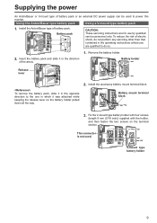
... mount terminal block 3. Fix the V-mount type battery holder with four screws (length 8 mm (5/16 inch)) supplied with the holder, and then fasten the two screws on the battery holder pulled down all the way. 2. Battery pack CAUTION: These servicing instructions are qualified to power this monitor. Install the accessory battery mount terminal block. This connector is not used to do so. 2. Remove the battery holder. Install...
... mount terminal block 3. Fix the V-mount type battery holder with four screws (length 8 mm (5/16 inch)) supplied with the holder, and then fasten the two screws on the battery holder pulled down all the way. 2. Battery pack CAUTION: These servicing instructions are qualified to power this monitor. Install the accessory battery mount terminal block. This connector is not used to do so. 2. Remove the battery holder. Install...
BTLH80W User Guide
Page 10
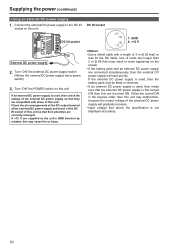
... removed. • If an external DC power supply is used, then make sure that their polarities are connected simultaneously, then the external DC power supply will gradually increase. • Input voltage that above the specification is used, then check the ratings of the external DC power supply so that they are compatible with a length of this unit. Turn "ON" the external DC power supply switch. (Where the external DC power supply has a power switch) 3. Check...
... removed. • If an external DC power supply is used, then make sure that their polarities are connected simultaneously, then the external DC power supply will gradually increase. • Input voltage that above the specification is used, then check the ratings of the external DC power supply so that they are compatible with a length of this unit. Turn "ON" the external DC power supply switch. (Where the external DC power supply has a power switch) 3. Check...
BTLH80W User Guide
Page 12
... is pushed. Various displays (warning of information are locked (→ page 30). Status display: PEAKING or PHASE CHROMA or FOCUS-IN-RED BRIGHT CONTRAST or BACKLIGHT 12 Battery level display • When an Anton/Bauer type digital battery is used, battery level is displayed. 7. "UNSUPPORT SIGNAL" and "NO SIGNAL" may not be adjusted after the display disappears. How to Use the On Screen Menu Six types of improper...
... is pushed. Various displays (warning of information are locked (→ page 30). Status display: PEAKING or PHASE CHROMA or FOCUS-IN-RED BRIGHT CONTRAST or BACKLIGHT 12 Battery level display • When an Anton/Bauer type digital battery is used, battery level is displayed. 7. "UNSUPPORT SIGNAL" and "NO SIGNAL" may not be adjusted after the display disappears. How to Use the On Screen Menu Six types of improper...
BTLH80W User Guide
Page 15
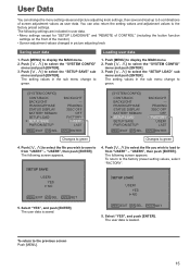
... the setting values and adjustment values to the factory preset settings. The setting values in picture adjusting knob Saving user data Loading user data 1. Push [ , ] to display the MAIN menu. 2. The setting values in the sub menu change the menu setting values and picture adjusting knob settings, then save to green. 1. Push [ , ] to select the file you wish to save and load up to 5 combinations of the monitor) • Screen adjustment values changed in the sub menu change to...
... the setting values and adjustment values to the factory preset settings. The setting values in picture adjusting knob Saving user data Loading user data 1. Push [ , ] to display the MAIN menu. 2. The setting values in the sub menu change the menu setting values and picture adjusting knob settings, then save to green. 1. Push [ , ] to select the file you wish to save and load up to 5 combinations of the monitor) • Screen adjustment values changed in the sub menu change to...
BTLH80W User Guide
Page 19
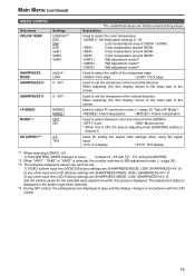
... sharpness values can each be set, 1) VIDEO system input line (VIDEO)(Factory settings are SHARPNESS MODE: LOW, SHARPNESS H/V: 0) 2) any other input line's HD (Factory settings are SHARPNESS MODE: HIGH, SHARPNESS H/V: 0) 3) any other input line's SD (Factory settings are factory preset setting values. Used for the selected input signal from within this is ON, the picture adjusting knob [CHROMA] setting is selected, the monitor switches to the lower part of the screen. Settings USER 63∗1 D93 D65 D56...
... sharpness values can each be set, 1) VIDEO system input line (VIDEO)(Factory settings are SHARPNESS MODE: LOW, SHARPNESS H/V: 0) 2) any other input line's HD (Factory settings are SHARPNESS MODE: HIGH, SHARPNESS H/V: 0) 3) any other input line's SD (Factory settings are factory preset setting values. Used for the selected input signal from within this is ON, the picture adjusting knob [CHROMA] setting is selected, the monitor switches to the lower part of the screen. Settings USER 63∗1 D93 D65 D56...
BTLH80W User Guide
Page 20
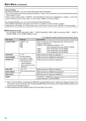
... are values adjusted before shipment from factories. -512 - 511 (Factory preset settings: 0) The underlined values are adjusted.∗2 "GAIN RED" - In such a case, "MODE 2" is recommended. Sub menu COLOR TEMP.∗1 GAIN RED GAIN GREEN GAIN BLUE BIAS RED BIAS GREEN BIAS BLUE RESET Settings USER 0 - 63 D93 D65 D56 0 - 511 (Factory presets are values for BLUE are factory preset setting values. Depending on still images, etc., flickers may occur on this screen return GAIN...
... are values adjusted before shipment from factories. -512 - 511 (Factory preset settings: 0) The underlined values are adjusted.∗2 "GAIN RED" - In such a case, "MODE 2" is recommended. Sub menu COLOR TEMP.∗1 GAIN RED GAIN GREEN GAIN BLUE BIAS RED BIAS GREEN BIAS BLUE RESET Settings USER 0 - 63 D93 D65 D56 0 - 511 (Factory presets are values for BLUE are factory preset setting values. Depending on still images, etc., flickers may occur on this screen return GAIN...
BTLH80W User Guide
Page 21
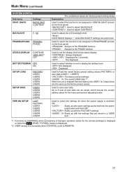
... power supply is set the display time for the menu and picture adjusting knobs. Displayed. Used to display the battery level. Always displayed. Displayed for the camera settings) is displayed or when the P-P (PIXEL TO PIXEL) status is displayed. ∗2 USER saving is not possible when CONTROL is switched ON. Used to adjust the LCD backlight level. Explanation Used to select the function to 5 sets of improper operation status for 3 seconds. Used to adjust BACKLIGHT. CONT./BACK displays "-" while BACKLIGHT settings are factory preset setting...
... power supply is set the display time for the menu and picture adjusting knobs. Displayed. Used to display the battery level. Always displayed. Displayed for the camera settings) is displayed or when the P-P (PIXEL TO PIXEL) status is displayed. ∗2 USER saving is not possible when CONTROL is switched ON. Used to adjust the LCD backlight level. Explanation Used to select the function to 5 sets of improper operation status for 3 seconds. Used to adjust BACKLIGHT. CONT./BACK displays "-" while BACKLIGHT settings are factory preset setting...
BTLH80W User Guide
Page 23
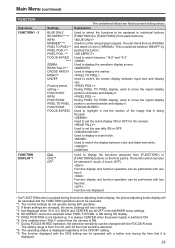
.... Used to switch between ON/OFF by pushing the button. Used to move the signal display position clockwise and display it . Function not displayed. • If a FUNCTION button is from [FUNCTION1] to switch the screen display between color and black-and-white. During PIXEL TO PIXEL display, used to switch the display between input size and display size. Used to [FUNCTION3] (buttons on the front panel). Used to display the waveform display screen. The setting range is pushed during the picture adjusting knobs display, the picture adjusting knobs display will also change...
.... Used to switch between ON/OFF by pushing the button. Used to move the signal display position clockwise and display it . Function not displayed. • If a FUNCTION button is from [FUNCTION1] to switch the screen display between color and black-and-white. During PIXEL TO PIXEL display, used to switch the display between input size and display size. Used to [FUNCTION3] (buttons on the front panel). Used to display the waveform display screen. The setting range is pushed during the picture adjusting knobs display, the picture adjusting knobs display will also change...
BTLH80W User Guide
Page 29
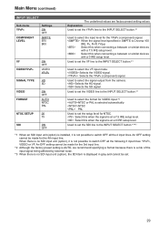
... setup level. Main Menu (continued) INPUT SELECT Sub menu YPBPR COMPONENT LEVEL Settings ON OFF SMPTE B75 B00 VF VIDEO/YPBPR SIGNAL TYPE VIDEO FORMAT NTSC SETUP SDI ON OFF VIDEO YPBPR HD SD ON OFF AUTO NTSC PAL 00 75 ON OFF The underlined values are factory preset setting values. Used to select the VF input mode. Used to set the SDI line to the INPUT SELECT button.∗...
... setup level. Main Menu (continued) INPUT SELECT Sub menu YPBPR COMPONENT LEVEL Settings ON OFF SMPTE B75 B00 VF VIDEO/YPBPR SIGNAL TYPE VIDEO FORMAT NTSC SETUP SDI ON OFF VIDEO YPBPR HD SD ON OFF AUTO NTSC PAL 00 75 ON OFF The underlined values are factory preset setting values. Used to select the VF input mode. Used to set the SDI line to the INPUT SELECT button.∗...
BTLH80W User Guide
Page 31
... the following terminals. Level operation (Connected: Monochrome, Open: Color) PIXEL TO PIXEL Switches the screen display between color and monochrome (MONO). Assignment items Function Operating conditions UNDEF No settings (no terminal assignment functions) - MARKER BACK BLACK∗2 Reduces the brightness of the image that is being displayed, this is possible on this monitor using HD signal) (Connected: 16:9, Open: 4:3) RED TALLY Lights the red tally. YPBPR Switches the input line to VF. Edge operation...
... the following terminals. Level operation (Connected: Monochrome, Open: Color) PIXEL TO PIXEL Switches the screen display between color and monochrome (MONO). Assignment items Function Operating conditions UNDEF No settings (no terminal assignment functions) - MARKER BACK BLACK∗2 Reduces the brightness of the image that is being displayed, this is possible on this monitor using HD signal) (Connected: 16:9, Open: 4:3) RED TALLY Lights the red tally. YPBPR Switches the input line to VF. Edge operation...
BTLH80W User Guide
Page 32
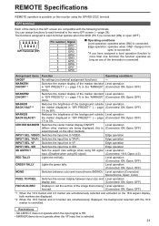
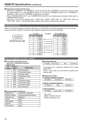
... about detailed systems which used the RS-232C. RS-232C REMOTE operation method Connectors and signal names Connector: D-SUB 9-pin (female) Signal name Pin Signal number name Explanation 1 N.C. Setting command response STX(02h) Command ETX(03h) 2. Query command response STX(02h) Data ETX(03h) 3. Error response STX(02h) Error code ETX(03h) Error code ER001: Invalid command ER002: Parameter error 32 VIDEO", "INPUT SEL. YPBPR" - RS-232C...
... about detailed systems which used the RS-232C. RS-232C REMOTE operation method Connectors and signal names Connector: D-SUB 9-pin (female) Signal name Pin Signal number name Explanation 1 N.C. Setting command response STX(02h) Command ETX(03h) 2. Query command response STX(02h) Data ETX(03h) 3. Error response STX(02h) Error code ETX(03h) Error code ER001: Invalid command ER002: Parameter error 32 VIDEO", "INPUT SEL. YPBPR" - RS-232C...
BTLH80W User Guide
Page 33
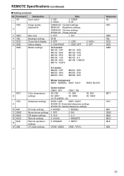
REMOTE Specifications (continued) Setting command No. Command Explanation 1 IIS Input switch VPC 2 Image quality adjustment 3 OBO 4 VBL 5 DCH 6 DSD DMK Blue only Backlight settings Cross hatch display Status display Marker settings Data 0: SDI 3: YPBPR 2: VIDEO 5: VF CON00-60 : Contrast settings BRI00-60 : Brightness settings CRO00-60 : Chroma settings PHA00-60 : Phase settings 0: OFF 1: ON 00-60 0: OFF 1: LOW 0: CONTINUE 1: 3SEC OFF 16:9 marker MK100 : OFF MK102 : 88% MK104 : 95% MK106 : 13...
REMOTE Specifications (continued) Setting command No. Command Explanation 1 IIS Input switch VPC 2 Image quality adjustment 3 OBO 4 VBL 5 DCH 6 DSD DMK Blue only Backlight settings Cross hatch display Status display Marker settings Data 0: SDI 3: YPBPR 2: VIDEO 5: VF CON00-60 : Contrast settings BRI00-60 : Brightness settings CRO00-60 : Chroma settings PHA00-60 : Phase settings 0: OFF 1: ON 00-60 0: OFF 1: LOW 0: CONTINUE 1: 3SEC OFF 16:9 marker MK100 : OFF MK102 : 88% MK104 : 95% MK106 : 13...
BTLH80W User Guide
Page 34
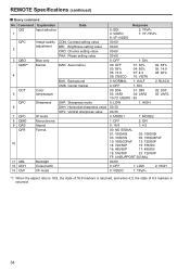
REMOTE Specifications (continued) Query command No. Command Explanation QIS Input selection 1 Data QPC 2 3 QBO QMK∗1 Image quality adjustment Blue only Marker CON: Contrast setting value BRI: Brightness setting value CRO: Chroma setting value PHA: Phase setting value MAK: Area marker 4 QCT 5 QPC 6 7 QPC 8 QMO 9 QAS QFR Color temperature BAK: Background CMK: Center marker Sharpness IP mode Monochrome Aspect Format SHP: Sharpness mode SHH: Horizontal sharpness value...
REMOTE Specifications (continued) Query command No. Command Explanation QIS Input selection 1 Data QPC 2 3 QBO QMK∗1 Image quality adjustment Blue only Marker CON: Contrast setting value BRI: Brightness setting value CRO: Chroma setting value PHA: Phase setting value MAK: Area marker 4 QCT 5 QPC 6 7 QPC 8 QMO 9 QAS QFR Color temperature BAK: Background CMK: Center marker Sharpness IP mode Monochrome Aspect Format SHP: Sharpness mode SHH: Horizontal sharpness value...
BTLH80W User Guide
Page 36
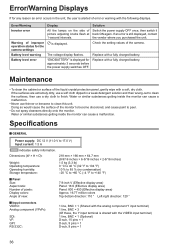
... following displays. Replace with a fully charged battery. Water or similar substances getting inside the monitor can cause a malfunction. If an error is displayed. Maintenance • To clean the cabinet or surface of view: 7.9-inch V (Effective display area) Panel: 16:9 (Effective display area) Panel: 800 × 450 (Effective display area) Approx. 16.77 million colors Top-bottom direction: 110 ° Left-right direction: 120 ° Input connectors VIDEO: Analog...
... following displays. Replace with a fully charged battery. Water or similar substances getting inside the monitor can cause a malfunction. If an error is displayed. Maintenance • To clean the cabinet or surface of view: 7.9-inch V (Effective display area) Panel: 16:9 (Effective display area) Panel: 800 × 450 (Effective display area) Approx. 16.77 million colors Top-bottom direction: 110 ° Left-right direction: 120 ° Input connectors VIDEO: Analog...


