
AWPH400 User Guide
Page 1
AW-RL400 AW-RC400 AW-RP400 AW-PH400 AW-PH400P Indoor Pan/Tilt Head AW-RP400N Pan/Tilt Control Panel AW-RC400N Cable Compensation Unit Roll Unit AW-RL400G AW-PH400 AW-RP400 AW-RC400 AW-RL400 Before attempting to connect, operate or adjust this product, please read these instructions completely.
AW-RL400 AW-RC400 AW-RP400 AW-PH400 AW-PH400P Indoor Pan/Tilt Head AW-RP400N Pan/Tilt Control Panel AW-RC400N Cable Compensation Unit Roll Unit AW-RL400G AW-PH400 AW-RP400 AW-RC400 AW-RL400 Before attempting to connect, operate or adjust this product, please read these instructions completely.
AWPH400 User Guide
Page 4
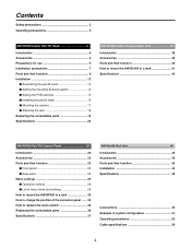
Contents Safety precautions 2 Operating precautions 5 AW-PH400 Indoor Pan/Tilt Head 6 Introduction 6 Accessories 6 Precautions for use 6 Installation precautions 7 Parts and their function 8 Installation 12 $ Assembling the pan/tilt head 12 $ Setting the...33 How to change the position of the connector panel ...... 34 How to replace the zoom switch 35 Replacing the consumable parts 36 Specifications 37 AW-RL400 Roll Unit 43 Introduction 43 Accessories 43 Parts and their function 44 Installation 45 Specifications 48 Connections 49 Example of system configuration 51 Operating...
Contents Safety precautions 2 Operating precautions 5 AW-PH400 Indoor Pan/Tilt Head 6 Introduction 6 Accessories 6 Precautions for use 6 Installation precautions 7 Parts and their function 8 Installation 12 $ Assembling the pan/tilt head 12 $ Setting the...33 How to change the position of the connector panel ...... 34 How to replace the zoom switch 35 Replacing the consumable parts 36 Specifications 37 AW-RL400 Roll Unit 43 Introduction 43 Accessories 43 Parts and their function 44 Installation 45 Specifications 48 Connections 49 Example of system configuration 51 Operating...
AWPH400 User Guide
Page 6
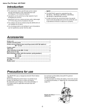
...domestic laws and regulations. NOTE ≥ The AW-PH400 cannot be controlled from the AW-RP301, AW-RP305, AW-RP501, AW-RP505, AW-RP605 or AW-RP605A controller. ≥ In order to protect the environment when the pan/tilt head is to be discarded at high speeds of up to 50 positions can be ...the general household garbage. Indoor Pan/Tilt Head AW-PH400 Introduction ≥ The stand-alone indoor pan/tilt head can be rotated through 300 degrees in the vertical direction and 400 degrees in the horizontal direction. ≥ Operations can be performed at the end of its printed circuit boards, ...
...domestic laws and regulations. NOTE ≥ The AW-PH400 cannot be controlled from the AW-RP301, AW-RP305, AW-RP501, AW-RP505, AW-RP605 or AW-RP605A controller. ≥ In order to protect the environment when the pan/tilt head is to be discarded at high speeds of up to 50 positions can be ...the general household garbage. Indoor Pan/Tilt Head AW-PH400 Introduction ≥ The stand-alone indoor pan/tilt head can be rotated through 300 degrees in the vertical direction and 400 degrees in the horizontal direction. ≥ Operations can be performed at the end of its printed circuit boards, ...
AWPH400 User Guide
Page 7
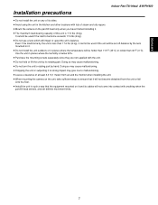
... impact may cause malfunctioning. ≥ Do not turn the unit's rotating part by the lens mounted on it and its rotating part. AW-PH400 Installation precautions Indoor Pan/Tilt Head AW-PH400 ≥ Do not install the unit on any of its sides. ≥ Avoid using the unit in the kitchen and other locations...
... impact may cause malfunctioning. ≥ Do not turn the unit's rotating part by the lens mounted on it and its rotating part. AW-PH400 Installation precautions Indoor Pan/Tilt Head AW-PH400 ≥ Do not install the unit on any of its sides. ≥ Avoid using the unit in the kitchen and other locations...

AWPH400 User Guide
Page 8
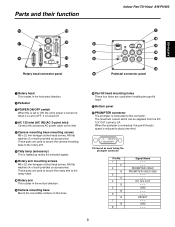
Indoor Pan/Tilt Head AW-PH400 Parts and their function 1 2 5 3 4 : ; < = > ? 8 6 7 8 9
Indoor Pan/Tilt Head AW-PH400 Parts and their function 1 2 5 3 4 : ; < = > ? 8 6 7 8 9
AWPH400 User Guide
Page 9
... These four holes are used when installing the pan/tilt head. ; Parts and their function @ C A D G H B E I F Rotary head connector panel J Indoor Pan/Tilt Head AW-PH400 K L M N O P Pedestal connector panel AW-PH400 1 Rotary head This rotates in the horizontal direction. 2 Pedestal 3 POWER ON/OFF switch When this is set to OFF, it is set to ON...
... These four holes are used when installing the pan/tilt head. ; Parts and their function @ C A D G H B E I F Rotary head connector panel J Indoor Pan/Tilt Head AW-PH400 K L M N O P Pedestal connector panel AW-PH400 1 Rotary head This rotates in the horizontal direction. 2 Pedestal 3 POWER ON/OFF switch When this is set to OFF, it is set to ON...
AWPH400 User Guide
Page 10
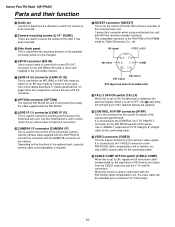
... to be used for the control of the ND filter and lens extender of the motorized lens unit. Use the camera cable supplied with the AW-PH400 to connect the connector with the connector. When it has been mounted. ? Use a BNC coaxial cable for the camera's video signals. A LENS I/F (2) connector [LENS... CGND EXT return EXT signal (Pin layout as seen from the VIDEO connector and the Y, Pr and Pb connectors. Indoor Pan/Tilt Head AW-PH400 Parts and their function = Guide pin Use this to determine the direction in which have been cablecompensated for the control of signals of the ...
... to be used for the control of the ND filter and lens extender of the motorized lens unit. Use the camera cable supplied with the AW-PH400 to connect the connector with the connector. When it has been mounted. ? Use a BNC coaxial cable for the camera's video signals. A LENS I/F (2) connector [LENS... CGND EXT return EXT signal (Pin layout as seen from the VIDEO connector and the Y, Pr and Pb connectors. Indoor Pan/Tilt Head AW-PH400 Parts and their function = Guide pin Use this to determine the direction in which have been cablecompensated for the control of signals of the ...

AWPH400 User Guide
Page 11
... coaxial cable for the connecting cable. It is the output connector for the prompter are input to the G/L OUT connector on the AW-RC400 cable compensation unit or monitor, etc. AW-PH400 Parts and their function J Y connector [Y] This is the genlock signal input connector. N PROMPTER IN connector [PROMPTER IN] The video signals for.... M G/L IN connector [G/L IN] This is the output connector for the connecting cable. Use a BNC coaxial cable for the camera's video signals. Indoor Pan/Tilt Head AW-PH400 11 When the AW-PB504 SDI card or other unit.
... coaxial cable for the connecting cable. It is the output connector for the prompter are input to the G/L OUT connector on the AW-RC400 cable compensation unit or monitor, etc. AW-PH400 Parts and their function J Y connector [Y] This is the genlock signal input connector. N PROMPTER IN connector [PROMPTER IN] The video signals for.... M G/L IN connector [G/L IN] This is the output connector for the connecting cable. Use a BNC coaxial cable for the camera's video signals. Indoor Pan/Tilt Head AW-PH400 11 When the AW-PB504 SDI card or other unit.

AWPH400 User Guide
Page 12
... assembling the pan/tilt head, use the Allen key (provided) and screwdriver, and secure the head by tightening the screws firmly. Indoor Pan/Tilt Head AW-PH400 Installation (Be sure to ask your dealer to the rotary arm. Camera Mounting base Change the positions of the camera mounting screws. After mounting the...
... assembling the pan/tilt head, use the Allen key (provided) and screwdriver, and secure the head by tightening the screws firmly. Indoor Pan/Tilt Head AW-PH400 Installation (Be sure to ask your dealer to the rotary arm. Camera Mounting base Change the positions of the camera mounting screws. After mounting the...

AWPH400 User Guide
Page 13
... lamp using the two screws provided. Mount the lamp while paying attention to ensure that they will not come loose during use. 13 AW-PH400 Indoor Pan/Tilt Head AW-PH400 Installation (Be sure to ask your dealer to install the unit.) 3 Mounting the tally lamp Connect the cable connector which is taped to...
... lamp using the two screws provided. Mount the lamp while paying attention to ensure that they will not come loose during use. 13 AW-PH400 Indoor Pan/Tilt Head AW-PH400 Installation (Be sure to ask your dealer to install the unit.) 3 Mounting the tally lamp Connect the cable connector which is taped to...

AWPH400 User Guide
Page 14
Indoor Pan/Tilt Head AW-PH400 Installation (Be sure to ask your dealer to install the unit.) $ Setting the mounting direction switch Set the switch as follows when the unit is ...
Indoor Pan/Tilt Head AW-PH400 Installation (Be sure to ask your dealer to install the unit.) $ Setting the mounting direction switch Set the switch as follows when the unit is ...
AWPH400 User Guide
Page 15
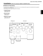
AW-PH400 Indoor Pan/Tilt Head AW-PH400 Installation (Be sure to ask your dealer to install the unit.) $ Setting the PCB switches The switches on the CONNECTOR PCB will need to be set in accordance with the signals to be transmitted and the equipment to be connected to the pan/tilt head. (The switches are set to support analog/SDI at the factory.) ≥ Analog/SDI support IP/IEEE switch: IEEE 422/IP switch: 422 ≥ Web card support IP/IEEE switch: IP 422/IP switch: IP ≥ IEEE1394 card support IP/IEEE switch: IEEE 422/IP switch: 422 IP/IEEE switch 422/IP switch 15
AW-PH400 Indoor Pan/Tilt Head AW-PH400 Installation (Be sure to ask your dealer to install the unit.) $ Setting the PCB switches The switches on the CONNECTOR PCB will need to be set in accordance with the signals to be transmitted and the equipment to be connected to the pan/tilt head. (The switches are set to support analog/SDI at the factory.) ≥ Analog/SDI support IP/IEEE switch: IEEE 422/IP switch: 422 ≥ Web card support IP/IEEE switch: IP 422/IP switch: IP ≥ IEEE1394 card support IP/IEEE switch: IEEE 422/IP switch: 422 IP/IEEE switch 422/IP switch 15
AWPH400 User Guide
Page 16
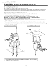
... the weight of the appropriate size to proceed as instructed. Do not install the pan/tilt head on its side since its prescribed operation and performance cannot be absolutely sure to tighten up the hexagon head bolts. ≥ When installing the pan/tilt head on the ceiling Wire t t ❈ ... has been installed, mount the camera on it will not make contact with any surrounding objects when the head is swiveled. Indoor Pan/Tilt Head AW-PH400 Installation (Be sure to ask your dealer to secure the pan/tilt head firmly. ≥ Use the M6 hexagon head bolts (including one short...
... the weight of the appropriate size to proceed as instructed. Do not install the pan/tilt head on its side since its prescribed operation and performance cannot be absolutely sure to tighten up the hexagon head bolts. ≥ When installing the pan/tilt head on the ceiling Wire t t ❈ ... has been installed, mount the camera on it will not make contact with any surrounding objects when the head is swiveled. Indoor Pan/Tilt Head AW-PH400 Installation (Be sure to ask your dealer to secure the pan/tilt head firmly. ≥ Use the M6 hexagon head bolts (including one short...
AWPH400 User Guide
Page 17
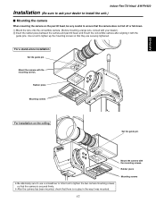
... it with the guide pins. For a stand-alone installation Set the guide pin. Mount the camera with the mounting screws. Mounting screws 17 AW-PH400 Indoor Pan/Tilt Head AW-PH400 Installation (Be sure to ask your dealer.) 2 Insert the rubber piece between the camera and pan/tilt head, and mount the convertible camera...
... it with the guide pins. For a stand-alone installation Set the guide pin. Mount the camera with the mounting screws. Mounting screws 17 AW-PH400 Indoor Pan/Tilt Head AW-PH400 Installation (Be sure to ask your dealer.) 2 Insert the rubber piece between the camera and pan/tilt head, and mount the convertible camera...

AWPH400 User Guide
Page 18
... washer) to attach the other end of the wire to the screw hole of the mounting spacer. When mounting the cameras without fan (AW-E350, AW-E650, AW-E300, AW-E300A, AW-E600) 1 Use the wire mounting screw (M4!8 mm with flat washer and spring washer) to attach one end of the wire to the... the other end of the wire to tighten up the mounting spacer and screws securely using a tool such as a screwdriver. 18 Indoor Pan/Tilt Head AW-PH400 Installation (Be sure to ask your dealer to bear the weight of the whole camera (camera + lens).
... washer) to attach the other end of the wire to the screw hole of the mounting spacer. When mounting the cameras without fan (AW-E350, AW-E650, AW-E300, AW-E300A, AW-E600) 1 Use the wire mounting screw (M4!8 mm with flat washer and spring washer) to attach one end of the wire to the... the other end of the wire to tighten up the mounting spacer and screws securely using a tool such as a screwdriver. 18 Indoor Pan/Tilt Head AW-PH400 Installation (Be sure to ask your dealer to bear the weight of the whole camera (camera + lens).

AWPH400 User Guide
Page 19
... your dealer. $ Replacing the belt Replace the belt when the preset stop accuracy has deteriorated. Replacing the consumable parts Indoor Pan/Tilt Head AW-PH400 $ Replacing the battery The battery has a service life of the arrow. 3 Attach the pedestal connector panel using the four screws. This ... side of the new battery to the front side, and insert its charge with a new one. (Battery used: CR2032 manganese dioxide-lithium battery) AW-PH400 $ How to remove the battery 1 Remove the four screws, and remove the pedestal connector panel. 2 Push the battery in the direction indicated by...
... your dealer. $ Replacing the belt Replace the belt when the preset stop accuracy has deteriorated. Replacing the consumable parts Indoor Pan/Tilt Head AW-PH400 $ Replacing the battery The battery has a service life of the arrow. 3 Attach the pedestal connector panel using the four screws. This ... side of the new battery to the front side, and insert its charge with a new one. (Battery used: CR2032 manganese dioxide-lithium battery) AW-PH400 $ How to remove the battery 1 Remove the four screws, and remove the pedestal connector panel. 2 Push the battery in the direction indicated by...

AWPH400 User Guide
Page 20
... setting. Specifications are approximate. The tilt range is limited to be mounted on pan/tilt head. Indoor Pan/Tilt Head AW-PH400 Specifications Supply voltage: AC 120 V, 60 Hz Power consumption: 145 W 1 indicates safety information. Genlock input: BNC Black burst or composite...IP RJ45, RS-485, pan/tilt head control signal output Connecting cable: 10BASE-T straight cable (equivalent to UTP category 5), max. 500 meters Functions/performance: Maximum load-bearing capacity: 17.6 lbs (8 kg) Tilt range: 300 degrees (approx. ±150 degrees) The tilt range is subject to ...
... setting. Specifications are approximate. The tilt range is limited to be mounted on pan/tilt head. Indoor Pan/Tilt Head AW-PH400 Specifications Supply voltage: AC 120 V, 60 Hz Power consumption: 145 W 1 indicates safety information. Genlock input: BNC Black burst or composite...IP RJ45, RS-485, pan/tilt head control signal output Connecting cable: 10BASE-T straight cable (equivalent to UTP category 5), max. 500 meters Functions/performance: Maximum load-bearing capacity: 17.6 lbs (8 kg) Tilt range: 300 degrees (approx. ±150 degrees) The tilt range is subject to ...
AWPH400 User Guide
Page 22
...-mounting adaptors 2 Mounting screws (M4!8 mm 4 22 Pan/Tilt Control Panel AW-RP400 Introduction ≥ This pan/tilt control panel enables up to five AW-PH400 indoor pan/tilt heads to be controlled. ≥ By connecting the AW-CB400 remote operation panel or WV-CB700A remote control box to the control panel...specialized contractor to dispose of it properly in order to a maximum of the pan/tilt head system must be set without fail. ≥ When the AW-RP400 control panel is to be discarded at the same time. ≥ Up to ten tracing memories can be accommodated. ≥ Up to 50 ...
...-mounting adaptors 2 Mounting screws (M4!8 mm 4 22 Pan/Tilt Control Panel AW-RP400 Introduction ≥ This pan/tilt control panel enables up to five AW-PH400 indoor pan/tilt heads to be controlled. ≥ By connecting the AW-CB400 remote operation panel or WV-CB700A remote control box to the control panel...specialized contractor to dispose of it properly in order to a maximum of the pan/tilt head system must be set without fail. ≥ When the AW-RP400 control panel is to be discarded at the same time. ≥ Up to ten tracing memories can be accommodated. ≥ Up to 50 ...

AWPH400 User Guide
Page 27
... and the images of 500 meters. Q DC 12V IN socket Connect the AW-PS505 AC adaptor (sold separately) to control the pan/tilt head systems from the MONITOR2 connector on the AW-PH400 indoor pan/tilt heads using a 10BASE-T (equivalent to UTP category 5) straight cables. Connect ...the connector to this connector using the AW-CA50T9 RS-232C cable. Pan/Tilt Control Panel AW-RP400 27 S MONI SEL OUT connector Connect this...
... and the images of 500 meters. Q DC 12V IN socket Connect the AW-PS505 AC adaptor (sold separately) to control the pan/tilt head systems from the MONITOR2 connector on the AW-PH400 indoor pan/tilt heads using a 10BASE-T (equivalent to UTP category 5) straight cables. Connect ...the connector to this connector using the AW-CA50T9 RS-232C cable. Pan/Tilt Control Panel AW-RP400 27 S MONI SEL OUT connector Connect this...

AWPH400 User Guide
Page 30
... (190/300 degrees) This menu item is used . setting (OFF/1/2/3) At the OFF setting, the pan and tilt speed does not change in accordance with a high magnification rate. conversely, the lower the setting, the slower the movement speed. The higher the number selected for the setting, the slower the pan and... is operated, the DIRECTION menu item enables the operational direction of PAN, TILT, ZOOM, FOCUS, IRIS or ROTATION to set the tilting range of the AW-PH400. TILT: When NORMAL is selected, the pan/tilt head moves upward when the PAN/TILT lever is tilted toward DOWN.
... (190/300 degrees) This menu item is used . setting (OFF/1/2/3) At the OFF setting, the pan and tilt speed does not change in accordance with a high magnification rate. conversely, the lower the setting, the slower the movement speed. The higher the number selected for the setting, the slower the pan and... is operated, the DIRECTION menu item enables the operational direction of PAN, TILT, ZOOM, FOCUS, IRIS or ROTATION to set the tilting range of the AW-PH400. TILT: When NORMAL is selected, the pan/tilt head moves upward when the PAN/TILT lever is tilted toward DOWN.
