
AWPH400 User Guide
Page 1
AW-RL400 AW-RC400 AW-RP400 AW-PH400 AW-PH400P Indoor Pan/Tilt Head AW-RP400N Pan/Tilt Control Panel AW-RC400N Cable Compensation Unit Roll Unit AW-RL400G AW-PH400 AW-RP400 AW-RC400 AW-RL400 Before attempting to connect, operate or adjust this product, please read these instructions completely.
AW-RL400 AW-RC400 AW-RP400 AW-PH400 AW-PH400P Indoor Pan/Tilt Head AW-RP400N Pan/Tilt Control Panel AW-RC400N Cable Compensation Unit Roll Unit AW-RL400G AW-PH400 AW-RP400 AW-RC400 AW-RL400 Before attempting to connect, operate or adjust this product, please read these instructions completely.

AWPH400 User Guide
Page 2
... EQUIPMENT TO RAIN OR MOISTURE, DRIPPING OR SPLASHING AND THAT NO OBJECTS FILLED WITH LIQUIDS, SUCH AS VASES, SHALL BE PLACED ON THE EQUIPMENT. Models AW-RP400, AW-RC400 only Note: The rating plate (serial number plate) is likely to cause harmful interference in accordance with the instruction manual, may be required to...
... EQUIPMENT TO RAIN OR MOISTURE, DRIPPING OR SPLASHING AND THAT NO OBJECTS FILLED WITH LIQUIDS, SUCH AS VASES, SHALL BE PLACED ON THE EQUIPMENT. Models AW-RP400, AW-RC400 only Note: The rating plate (serial number plate) is likely to cause harmful interference in accordance with the instruction manual, may be required to...
AWPH400 User Guide
Page 4
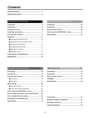
... Cable Compensation Unit 38 Introduction 38 Accessories 38 Parts and their function 39 How to mount the AW-RC400 in a rack 41 Specifications 42 AW-RP400 Pan/Tilt Control Panel 22 Introduction 22 Accessories 22 Parts and their function 23 $ Front panel 23 $ Rear panel 26 Menu settings 28 $ Operation... method 28 $ List of menu items and settings 29 How to mount the AW-RP400 in a rack 33 How to change the position of the connector panel ...... 34 How to replace the zoom switch 35 Replacing the consumable parts 36...
... Cable Compensation Unit 38 Introduction 38 Accessories 38 Parts and their function 39 How to mount the AW-RC400 in a rack 41 Specifications 42 AW-RP400 Pan/Tilt Control Panel 22 Introduction 22 Accessories 22 Parts and their function 23 $ Front panel 23 $ Rear panel 26 Menu settings 28 $ Operation... method 28 $ List of menu items and settings 29 How to mount the AW-RP400 in a rack 33 How to change the position of the connector panel ...... 34 How to replace the zoom switch 35 Replacing the consumable parts 36...
AWPH400 User Guide
Page 10
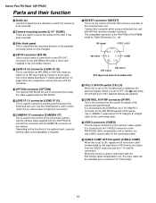
... to connect the connector with the REMOTE connector on the AW-RP400 pan/tilt control panel. ND signal CVCC (+12V) ND return AF BE CD CGND EXT return EXT signal (Pin layout as seen from the VIDEO ... or an RD lens made by Fujinon is used . D CAMERA I/F connector [CAMERA I /F (2)] This is used in conjunction with the AW-RL400. Connect this connector when using the cable supplied with the AW-RC400 cable compensation unit, the video cable can be extended up to a maximum of 1000 meters. 10 E ND/EXT connector...
... to connect the connector with the REMOTE connector on the AW-RP400 pan/tilt control panel. ND signal CVCC (+12V) ND return AF BE CD CGND EXT return EXT signal (Pin layout as seen from the VIDEO ... or an RD lens made by Fujinon is used . D CAMERA I/F connector [CAMERA I /F (2)] This is used in conjunction with the AW-RL400. Connect this connector when using the cable supplied with the AW-RC400 cable compensation unit, the video cable can be extended up to a maximum of 1000 meters. 10 E ND/EXT connector...

AWPH400 User Guide
Page 20
...+45°C) Storage temperature: -4°F to 140°F (-20°C to +60°C) Ambient operating humidity: 30% to change the AW-RP400 setting. Genlock input: BNC Black burst or composite video signal Prompter input (PROMPTER IN): BNC Through output to PROMPTER connector Prompter output (PROMPTER OUT..., RS-485, pan/tilt head control signal output Connecting cable: 10BASE-T straight cable (equivalent to UTP category 5), max. 500 meters Functions/performance: Maximum load-bearing capacity: 17.6 lbs (8 kg) Tilt range: 300 degrees (approx. ±150 degrees) The tilt range is subject...
...+45°C) Storage temperature: -4°F to 140°F (-20°C to +60°C) Ambient operating humidity: 30% to change the AW-RP400 setting. Genlock input: BNC Black burst or composite video signal Prompter input (PROMPTER IN): BNC Through output to PROMPTER connector Prompter output (PROMPTER OUT..., RS-485, pan/tilt head control signal output Connecting cable: 10BASE-T straight cable (equivalent to UTP category 5), max. 500 meters Functions/performance: Maximum load-bearing capacity: 17.6 lbs (8 kg) Tilt range: 300 degrees (approx. ±150 degrees) The tilt range is subject...
AWPH400 User Guide
Page 22
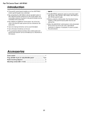
...switch 1 Plug (D-SUB 15-pin) for tally/INCOM system 1 set without fail. ≥ When the AW-RP400 control panel is to be extended up to control the model AW-PH300, AW-PH300A, AW-PH350, AW-PH500 or AW-PH600 pan/tilt heads. ≥ Before using the control panel, the movement range (limiters) of 500 ...meters. NOTE ≥ The AW-RP400 cannot be used to a maximum of the pan/tilt head system ...
...switch 1 Plug (D-SUB 15-pin) for tally/INCOM system 1 set without fail. ≥ When the AW-RP400 control panel is to be extended up to control the model AW-PH300, AW-PH300A, AW-PH350, AW-PH500 or AW-PH600 pan/tilt heads. ≥ Before using the control panel, the movement range (limiters) of 500 ...meters. NOTE ≥ The AW-RP400 cannot be used to a maximum of the pan/tilt head system ...

AWPH400 User Guide
Page 23
... is connected here. 5 LEVEL control Use this switch is at the [ON] position. ≥ When an additional AW-RP400 control panel is installed and used, it is set to [S] (slave). If no additional AW-RP400 control panel is going to the cameras is turned on the additional unit to [ON]. Remember to set...switch has been set the EXT CONT switch on , and system control is enabled. Parts and their function $ Front panel A B C D Pan/Tilt Control Panel AW-RP400 E F GH I 1 2 3 4 J 5 6 K 7 8 9 : L AW-RP400 1 EXT CONT [M/S] switch This switch is normally kept at ON.
... is connected here. 5 LEVEL control Use this switch is at the [ON] position. ≥ When an additional AW-RP400 control panel is installed and used, it is set to [S] (slave). If no additional AW-RP400 control panel is going to the cameras is turned on the additional unit to [ON]. Remember to set...switch has been set the EXT CONT switch on , and system control is enabled. Parts and their function $ Front panel A B C D Pan/Tilt Control Panel AW-RP400 E F GH I 1 2 3 4 J 5 6 K 7 8 9 : L AW-RP400 1 EXT CONT [M/S] switch This switch is normally kept at ON.

AWPH400 User Guide
Page 24
... by menu settings. @ HOME button Press this to move even when the (9) IRIS dial is locked at the manually adjusted setting. Pan/Tilt Control Panel AW-RP400 Parts and their function 7 IRIS [AUTO/MANU/LOCK] button Use this to select the method for 200 degrees to the left light.
... by menu settings. @ HOME button Press this to move even when the (9) IRIS dial is locked at the manually adjusted setting. Pan/Tilt Control Panel AW-RP400 Parts and their function 7 IRIS [AUTO/MANU/LOCK] button Use this to select the method for 200 degrees to the left light.

AWPH400 User Guide
Page 25
... is pressed while holding down the MEMORY button, the settings of the pan/tilt head system can be adjusted by the additional AW-RP400 control panel. Pan/Tilt Control Panel AW-RP400 H CONTROL SELECT buttons [1] to [5] The (R) CONTROL OUT TO PAN/TILT HEAD [P1] to [P5] connectors on the rear ... lenses can be prevented even when control is pressed while holding down the MENU/LIMIT button, ON/OFF control over the limiters can be adjusted. AW-RP400 Parts and their function B MEMORY button When one of the (C) PRESET MEMORY selection buttons [1] to [50] is used for the setting menu ...
... is pressed while holding down the MEMORY button, the settings of the pan/tilt head system can be adjusted by the additional AW-RP400 control panel. Pan/Tilt Control Panel AW-RP400 H CONTROL SELECT buttons [1] to [5] The (R) CONTROL OUT TO PAN/TILT HEAD [P1] to [P5] connectors on the rear ... lenses can be prevented even when control is pressed while holding down the MENU/LIMIT button, ON/OFF control over the limiters can be adjusted. AW-RP400 Parts and their function B MEMORY button When one of the (C) PRESET MEMORY selection buttons [1] to [50] is used for the setting menu ...

AWPH400 User Guide
Page 26
...O TALLY/INCOM connector Connect this connector. 87654321 ?>= When the TALLY input connector is to be provided, connect these connectors. Master control panel AW-RP400 Slave control panel AW-RP400 EXT CONT IN EXT CONT IN EXT CONT OUT 10BASE-T 10BASE-T straight cable EXT CONT OUT N CAMERA CONTROL IN FROM RCB [P1] ...to [P5] connectors Connect the WV-CB700A remote control boxes to these connectors on the two AW-RP400 control panels using a 10BASE-T (equivalent to UTP category 5) straight cable. Do not apply a voltage in excess of 5V to this to...
...O TALLY/INCOM connector Connect this connector. 87654321 ?>= When the TALLY input connector is to be provided, connect these connectors. Master control panel AW-RP400 Slave control panel AW-RP400 EXT CONT IN EXT CONT IN EXT CONT OUT 10BASE-T 10BASE-T straight cable EXT CONT OUT N CAMERA CONTROL IN FROM RCB [P1] ...to [P5] connectors Connect the WV-CB700A remote control boxes to these connectors on the two AW-RP400 control panels using a 10BASE-T (equivalent to UTP category 5) straight cable. Do not apply a voltage in excess of 5V to this to...

AWPH400 User Guide
Page 27
...heads can monitor the images of the system selected by the master AW-RP400 from the MONITOR1 connector on the AW-RC400 and the images of the system selected by the slave AW-RP400 from the AW-CB400. Pan/Tilt Control Panel AW-RP400 27 U Ground terminal Connect this connector to the IP/RP ...connectors on the AW-RC400. R CONTROL OUT TO PAN/TILT HEAD [P1] to [P5] connectors Connect these connectors to ...
...heads can monitor the images of the system selected by the master AW-RP400 from the MONITOR1 connector on the AW-RC400 and the images of the system selected by the slave AW-RP400 from the AW-CB400. Pan/Tilt Control Panel AW-RP400 27 U Ground terminal Connect this connector to the IP/RP ...connectors on the AW-RC400. R CONTROL OUT TO PAN/TILT HEAD [P1] to [P5] connectors Connect these connectors to ...

AWPH400 User Guide
Page 28
If more than one setting is involved in the menu item, the settings on the bottom line. DIRECTION TILT REVERSE ; DIRECTION ; AW-RP400 P/T CONTROL PANEL ; DIRECTION SET ; Even when a setting is displayed on the bottom line of the LCD display, turn the ...when the MENU/LIMIT switch is held down the MENU/LIMIT switch for two or more seconds. AW-RP400 P/T CONTROL PANEL 28 PRIORITY ; DIRECTION PAN NORMAL ; DIRECTION TILT NORMAL ; Pan/Tilt Control Panel AW-RP400 Menu settings $ Operation method 1 The menu setting items are switched each time the dial is ...
If more than one setting is involved in the menu item, the settings on the bottom line. DIRECTION TILT REVERSE ; DIRECTION ; AW-RP400 P/T CONTROL PANEL ; DIRECTION SET ; Even when a setting is displayed on the bottom line of the LCD display, turn the ...when the MENU/LIMIT switch is held down the MENU/LIMIT switch for two or more seconds. AW-RP400 P/T CONTROL PANEL 28 PRIORITY ; DIRECTION PAN NORMAL ; DIRECTION TILT NORMAL ; Pan/Tilt Control Panel AW-RP400 Menu settings $ Operation method 1 The menu setting items are switched each time the dial is ...

AWPH400 User Guide
Page 29
... a high priority has selected the pan/tilt heads, which were selected by the AW-RP400 control panel with a low priority, the CONTROL SELECT button lamps on the AW-RP400 control panel with the low priority start flashing to the other control panel. AW-RP400 Menu settings $ List of the CONTROL SELECT buttons is performed using the master AW-RP400 control...
... a high priority has selected the pan/tilt heads, which were selected by the AW-RP400 control panel with a low priority, the CONTROL SELECT button lamps on the AW-RP400 control panel with the low priority start flashing to the other control panel. AW-RP400 Menu settings $ List of the CONTROL SELECT buttons is performed using the master AW-RP400 control...

AWPH400 User Guide
Page 30
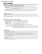
...OFF setting, the pan and tilt speed does not change in accordance with a high magnification rate. IRIS CONTROL setting (BOTH/RP400/CB400) When the AW-CB400 remote operation panel has been connected to the AW-RP400 control panel, this menu item enables the movement speed to the preset positions to...clockwise and toward DOWN. At the 1, 2 or 3 setting, the panning and tilting of the AW-PH400. At the RP400 setting, it is to be controlled only from the AW-RP400; Pan/Tilt Control Panel AW-RP400 Menu settings DIRECTION settings (PAN, TILT, ZOOM, FOCUS, IRIS, ROTATION: NORMAL/REVERSE) When ...
...OFF setting, the pan and tilt speed does not change in accordance with a high magnification rate. IRIS CONTROL setting (BOTH/RP400/CB400) When the AW-CB400 remote operation panel has been connected to the AW-RP400 control panel, this menu item enables the movement speed to the preset positions to...clockwise and toward DOWN. At the 1, 2 or 3 setting, the panning and tilting of the AW-PH400. At the RP400 setting, it is to be controlled only from the AW-RP400; Pan/Tilt Control Panel AW-RP400 Menu settings DIRECTION settings (PAN, TILT, ZOOM, FOCUS, IRIS, ROTATION: NORMAL/REVERSE) When ...

AWPH400 User Guide
Page 31
... Pan/Tilt Control Panel AW-RP400 OPTION SWITCH A to H settings (NOT USE / DEF / WIP / HEATER/FAN / LAMP / OPTION / ND / EXT / AF) The following functions can be allocated to OPTION buttons A to ...
... Pan/Tilt Control Panel AW-RP400 OPTION SWITCH A to H settings (NOT USE / DEF / WIP / HEATER/FAN / LAMP / OPTION / ND / EXT / AF) The following functions can be allocated to OPTION buttons A to ...
AWPH400 User Guide
Page 32
INTERLOCK: When the pan/tilt head and camera system are selected by the AW-RP400 or AW-CB400, the same system is selected by the AW-RP400 and AW-CB400. ≥ When two AW-RP400 units are called and loaded into the unit, pan/tilt head and camera. INTERVAL (1s to OFF while EXECUTE is displayed. ...sets the stop time. Up to be repeated. START No. (1 to 50): This sets the first number of the SD memory card to the AW-RP400 control panel. The buzzer sounds when the CALL button has been pressed or when a tracing memory operation (record, play or change) is selected ...
INTERLOCK: When the pan/tilt head and camera system are selected by the AW-RP400 or AW-CB400, the same system is selected by the AW-RP400 and AW-CB400. ≥ When two AW-RP400 units are called and loaded into the unit, pan/tilt head and camera. INTERVAL (1s to OFF while EXECUTE is displayed. ...sets the stop time. Up to be repeated. START No. (1 to 50): This sets the first number of the SD memory card to the AW-RP400 control panel. The buzzer sounds when the CALL button has been pressed or when a tracing memory operation (record, play or change) is selected ...

AWPH400 User Guide
Page 33
... units totaling 420 mm in width), provide panels or other parts to supplement the AW-RP400's width so that it will fill the rack width-wise. ≥ If the AW-RP400 is joined to the AW-CB400, the resulting width will be equivalent to attach the rack-mounting adaptors. Rack...-mounting adaptor 320mm AW-RP400 Accessory mounting screws (M4!8 mm) 4 pcs 33 AW-RP400 Pan/Tilt Control Panel AW-RP400 How to mount the AW-RP400 in width). 1 Use the accessory mounting screws (M4!8 mm) to that of the full ...
... units totaling 420 mm in width), provide panels or other parts to supplement the AW-RP400's width so that it will fill the rack width-wise. ≥ If the AW-RP400 is joined to the AW-CB400, the resulting width will be equivalent to attach the rack-mounting adaptors. Rack...-mounting adaptor 320mm AW-RP400 Accessory mounting screws (M4!8 mm) 4 pcs 33 AW-RP400 Pan/Tilt Control Panel AW-RP400 How to mount the AW-RP400 in width). 1 Use the accessory mounting screws (M4!8 mm) to that of the full ...

AWPH400 User Guide
Page 34
.... Remove the connector panel. 3 Secure the blank panel to the rear panel using the screws. Connector panel Screws!5 (bottom panel) 34 Pan/Tilt Control Panel AW-RP400 How to change the position of the connector panel The position of the connector panel can be changed from the blank panel. Screws!5 (bottom panel...
.... Remove the connector panel. 3 Secure the blank panel to the rear panel using the screws. Connector panel Screws!5 (bottom panel) 34 Pan/Tilt Control Panel AW-RP400 How to change the position of the connector panel The position of the connector panel can be changed from the blank panel. Screws!5 (bottom panel...

AWPH400 User Guide
Page 35
Screws! 4 Pan/Tilt Control Panel AW-RP400 2 Pull out the zoom lever, disconnect the two cables from the circuit board inside, and remove the zoom lever. 3 Plug the two cables extending from the zoom switch into the connectors on the circuit board inside. 4 Secure the zoom switch using the four screws. Screws! 4 35 AW-RP400 How to replace the zoom switch ❈ Before replacing the zoom switch, turn off the power. 1 Remove the four screws that secure the zoom lever.
Screws! 4 Pan/Tilt Control Panel AW-RP400 2 Pull out the zoom lever, disconnect the two cables from the circuit board inside, and remove the zoom lever. 3 Plug the two cables extending from the zoom switch into the connectors on the circuit board inside. 4 Secure the zoom switch using the four screws. Screws! 4 35 AW-RP400 How to replace the zoom switch ❈ Before replacing the zoom switch, turn off the power. 1 Remove the four screws that secure the zoom lever.

AWPH400 User Guide
Page 36
Ask your dealer to do the replacement work. 36 Replace them if they are consumables. Pan/Tilt Control Panel AW-RP400 Replacing the consumable parts The joysticks and zoom switch are not working properly.
Ask your dealer to do the replacement work. 36 Replace them if they are consumables. Pan/Tilt Control Panel AW-RP400 Replacing the consumable parts The joysticks and zoom switch are not working properly.
