Basic Operating Instructions
Page 1
Before operating this product, please read the instructions carefully and save this Compact Live Switcher and how to establish its settings, refer to the "Operations and Settings" manual (PDF file) which can be found on the CD-ROM supplied with the camera. 3TR006512BAA Operating Instructions Compact Live Switcher AW-HS50N Model No. For instructions on how to operate this manual for future use.
Before operating this product, please read the instructions carefully and save this Compact Live Switcher and how to establish its settings, refer to the "Operations and Settings" manual (PDF file) which can be found on the CD-ROM supplied with the camera. 3TR006512BAA Operating Instructions Compact Live Switcher AW-HS50N Model No. For instructions on how to operate this manual for future use.

Basic Operating Instructions
Page 2
... electric shock or fire hazard due to overheating, ensure that an apparatus with CLASS 1 construction shall be connected to a MAINS socket outlet with the instruction manual, may be correctly wired to provide connection to correct the interference at his own expense. Safety precautions CAUTION RISK OF ELECTRIC SHOCK DO NOT OPEN...
... electric shock or fire hazard due to overheating, ensure that an apparatus with CLASS 1 construction shall be connected to a MAINS socket outlet with the instruction manual, may be correctly wired to provide connection to correct the interference at his own expense. Safety precautions CAUTION RISK OF ELECTRIC SHOCK DO NOT OPEN...
Basic Operating Instructions
Page 4
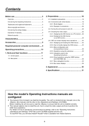
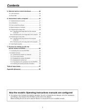
... OSD menus on -screen display) menu operations 24 2-5-1. Displaying and clearing the OSD menus .........24 2-5-2. Indications used in this manual), and the other devices 19 2-2-1. Parts and their functions 11 1-1. How to forcibly display the OSD menus ...........24 2-5-3. Preparations... 18 2-1. Specifications 31 How the model's Operating Instructions manuals are configured The manual of this Compact Live Switcher (hereafter, "the unit") is divided into two manuals: one is the (this Operating Instructions 27 2-5-6. To read ...
... OSD menus on -screen display) menu operations 24 2-5-1. Displaying and clearing the OSD menus .........24 2-5-2. Indications used in this manual), and the other devices 19 2-2-1. Parts and their functions 11 1-1. How to forcibly display the OSD menus ...........24 2-5-3. Preparations... 18 2-1. Specifications 31 How the model's Operating Instructions manuals are configured The manual of this Compact Live Switcher (hereafter, "the unit") is divided into two manuals: one is the (this Operating Instructions 27 2-5-6. To read ...

Basic Operating Instructions
Page 9
... 50 MB of free memory Other CD-ROM drive (for using the Operating Instructions and various software) Adobe® Reader® (for . Operating Instructions (this manual 1 CD-ROM 1 Operating Instructions Operating Instructions Data Transmission Software AC adapter 1 Power cable (2 m [6.6 ft 1 Required personal computer environment Run...
... 50 MB of free memory Other CD-ROM drive (for using the Operating Instructions and various software) Adobe® Reader® (for . Operating Instructions (this manual 1 CD-ROM 1 Operating Instructions Operating Instructions Data Transmission Software AC adapter 1 Power cable (2 m [6.6 ft 1 Required personal computer environment Run...

Basic Operating Instructions
Page 13
... screen. Lights Now fading in from the midway status. If the AUTO button is pressed while auto transition is being executed, operation will switch to manual as soon as the screen to which the program image is to be changed . FTB ON button [FTB ON] Press this button to fade... in . Press the button. Button indicator OFF: The transition is executed. When the button is pressed again, the program image is used when executing transitions manually. 1.
... screen. Lights Now fading in from the midway status. If the AUTO button is pressed while auto transition is being executed, operation will switch to manual as soon as the screen to which the program image is to be changed . FTB ON button [FTB ON] Press this button to fade... in . Press the button. Button indicator OFF: The transition is executed. When the button is pressed again, the program image is used when executing transitions manually. 1.

Basic Operating Instructions
Page 25
...display the items which are displayed on more than one page When a menu contains many setting items, they are hidden. In this manual, only one page. 25 Setting the USER buttons" ( Operating Instructions). In this screen. Moving between menus ...is displayed, turn the OSD/TIME dial on the last line of more than one page. The settings can be changed on this manual, the menu screens are always shown without the area where the USER button statuses are displayed except under special circumstances. ...
...display the items which are displayed on more than one page When a menu contains many setting items, they are hidden. In this manual, only one page. 25 Setting the USER buttons" ( Operating Instructions). In this screen. Moving between menus ...is displayed, turn the OSD/TIME dial on the last line of more than one page. The settings can be changed on this manual, the menu screens are always shown without the area where the USER button statuses are displayed except under special circumstances. ...

Operating Instructions
Page 2
Manual transitions 6 1-1-7. Selecting the wipe pattern 8 1-2-2. Adjusting the border color 9 1-2-6. Concerning key combinations 10 1-3-2. Setting the PinP and KEY priority 10 1-3-3. Chroma key adjustments 15 1-4. Selecting ...
Manual transitions 6 1-1-7. Selecting the wipe pattern 8 1-2-2. Adjusting the border color 9 1-2-6. Concerning key combinations 10 1-3-2. Setting the PinP and KEY priority 10 1-3-3. Chroma key adjustments 15 1-4. Selecting ...
Operating Instructions
Page 3
... the unit 51 6-6-2. Data transmission functions 47 6-2. Basic operations of this Compact Live Switcher (hereafter, "the unit") is divided into two manuals: one is the (this manual in the CD-ROM), and the other is installed correctly. 3 Before installing the unit, be sure to read the to the... AW-RP50 53 7-2. Connections 47 6-3. Transferring the image data from the computer to the computer ..... 51 6-7. Transferring the unit's setup data to the ...
... the unit 51 6-6-2. Data transmission functions 47 6-2. Basic operations of this Compact Live Switcher (hereafter, "the unit") is divided into two manuals: one is the (this manual in the CD-ROM), and the other is installed correctly. 3 Before installing the unit, be sure to read the to the... AW-RP50 53 7-2. Connections 47 6-3. Transferring the image data from the computer to the computer ..... 51 6-7. Transferring the unit's setup data to the ...

Operating Instructions
Page 6
... replaced PGM materials, and the signals selected by the B bus are replaced PGM materials. When only indicator A is lighted: Only the A bus is to manual as soon as the position of the slide lever has gone beyond the amount of the lever show the program output statuses... Operate the slide lever to select the background transition mode. 1-1-6. Selecting the transition type Use the MIX button and WIPE button to execute transitions manually. If the slide lever is moved while an auto transition is output [13] Operation Menu 7. 1. Bus Mode A/B: When the slide lever is at side B, ...
... replaced PGM materials, and the signals selected by the B bus are replaced PGM materials. When only indicator A is lighted: Only the A bus is to manual as soon as the position of the slide lever has gone beyond the amount of the lever show the program output statuses... Operate the slide lever to select the background transition mode. 1-1-6. Selecting the transition type Use the MIX button and WIPE button to execute transitions manually. If the slide lever is moved while an auto transition is output [13] Operation Menu 7. 1. Bus Mode A/B: When the slide lever is at side B, ...

Operating Instructions
Page 19
... area which has been set using the "7. Select 1, 2, 3 or 4, and press the OSD/TIME dial. USER1 19 Trim Adjust1 8. Trim Adjust1" and "8. Trim Adjust1" and "8. Manual: The image is 4:3. Trim Adjust2 The method of the trimming area. Trim Adjust2" items. Set the values for left (L), top (T), right (R) and bottom (B) of trimming...
... area which has been set using the "7. Select 1, 2, 3 or 4, and press the OSD/TIME dial. USER1 19 Trim Adjust1 8. Trim Adjust1" and "8. Trim Adjust1" and "8. Manual: The image is 4:3. Trim Adjust2 The method of the trimming area. Trim Adjust2" items. Set the values for left (L), top (T), right (R) and bottom (B) of trimming...

Operating Instructions
Page 21
... be prevented. [10] Input Menu 1. DbyD: The images are enabled. Effect dissolve This function enables one effect to another smoothly when the data in the Manual mode) 1-4-6. PinP EFFDSLV Image position (X, Y) Image size Border width Border color Soft effect amount Trimming area setting (Value which...
... be prevented. [10] Input Menu 1. DbyD: The images are enabled. Effect dissolve This function enables one effect to another smoothly when the data in the Manual mode) 1-4-6. PinP EFFDSLV Image position (X, Y) Image size Border width Border color Soft effect amount Trimming area setting (Value which...

Operating Instructions
Page 26
... the flash memory The data of storing the image data in the frame memory is displayed on the OSD menu. Auto: The images are stored manually. Do not turn off by saving it...
... the flash memory The data of storing the image data in the frame memory is displayed on the OSD menu. Auto: The images are stored manually. Do not turn off by saving it...

Operating Instructions
Page 27
... Input connector SDI IN 1, SDI IN 2 SDI IN 3, SDI IN 4 DVI IN VPrc 2-1-6 Setting menu items and sections in this manual Name Type Name Freeze Select 2-1-1 2-1-2 2-1-3 2-1-4 SDI IN 1, SDI IN 2 SDI IN 3, SDI IN 4 &#...2-1. Name" items described below by the input signals selected. Input signal settings The SDI IN 1 to SDI IN 4 connectors are displayed in this manual UC DVI-IN scaling DVI-IN information display 2-1-7 2-1-8 2-1-9 - - - - - - - &#...
... Input connector SDI IN 1, SDI IN 2 SDI IN 3, SDI IN 4 DVI IN VPrc 2-1-6 Setting menu items and sections in this manual Name Type Name Freeze Select 2-1-1 2-1-2 2-1-3 2-1-4 SDI IN 1, SDI IN 2 SDI IN 3, SDI IN 4 &#...2-1. Name" items described below by the input signals selected. Input signal settings The SDI IN 1 to SDI IN 4 connectors are displayed in this manual UC DVI-IN scaling DVI-IN information display 2-1-7 2-1-8 2-1-9 - - - - - - - &#...

Operating Instructions
Page 44
... to "5-2. Disable: Control is disabled. For details on what is used to be changed easily. 44 Time Unit Refer to "1-1-4. Manual transitions". [13] Operation Menu 8. Disable: Control is disabled. For details on what is not desirable for linking up with the... AW-RP50 to change the [14] SYSTEM Menu settings. Other settings [13] Operation Menu 4. Selecting the bus mode". [13] Operation Menu 6. Select this ...
... to "5-2. Disable: Control is disabled. For details on what is used to be changed easily. 44 Time Unit Refer to "1-1-4. Manual transitions". [13] Operation Menu 8. Disable: Control is disabled. For details on what is not desirable for linking up with the... AW-RP50 to change the [14] SYSTEM Menu settings. Other settings [13] Operation Menu 4. Selecting the bus mode". [13] Operation Menu 6. Select this ...

Operating Instructions
Page 57
... range White, Yellow, Cyan, Green, Magenta, Red, Blue, Black Initial value White Setting range 0.0 to 359.9 H Initial value 0.0 0.0 to 100.0 S 0.0 0.0 to 108.0 L 100.0 Setting range Manual, Off, 4:3 Initial value Off -50.00 to 50.00 L -40.00 -50.00 to 50.00 T 40.00 Setting range -50.00 to 50.00...
... range White, Yellow, Cyan, Green, Magenta, Red, Blue, Black Initial value White Setting range 0.0 to 359.9 H Initial value 0.0 0.0 to 100.0 S 0.0 0.0 to 108.0 L 100.0 Setting range Manual, Off, 4:3 Initial value Off -50.00 to 50.00 L -40.00 -50.00 to 50.00 T 40.00 Setting range -50.00 to 50.00...

Operating Instructions
Page 65
... line output signals. Clip The threshold level of the video serial interface. Color Background The signals which is executed with no accompanying deterioration in this manual. Embedded Audio This refers to one frame. Aspect ratio The ratio between the horizontal and vertical dimensions of the video signals. Freeze A function which are...
... line output signals. Clip The threshold level of the video serial interface. Color Background The signals which is executed with no accompanying deterioration in this manual. Embedded Audio This refers to one frame. Aspect ratio The ratio between the horizontal and vertical dimensions of the video signals. Freeze A function which are...

How-To Store Still Images in HS50 AUX Frame Memory
Page 1
...buttons, select the input image to be stored. - (Fig. 1-B) ③ Press AUX button to release the AUX bus material selection mode. (Figure 1: AW-HS50 Control Panel) (D) (C) (A) (B) (Transferring images from AUX bus) ④ Hold down the button again.) ⑤...Memories (with AUX Bus) ★ Still images can be stored in AW-HS50 switcher's two built-in memories (FMEM 1 & 2) to select the destination and then execute the import. (Destination) - [12] USER/FMEM Menu > 5. This Manual will give you the explanation of "how to use AUX bus" when...
...buttons, select the input image to be stored. - (Fig. 1-B) ③ Press AUX button to release the AUX bus material selection mode. (Figure 1: AW-HS50 Control Panel) (D) (C) (A) (B) (Transferring images from AUX bus) ④ Hold down the button again.) ⑤...Memories (with AUX Bus) ★ Still images can be stored in AW-HS50 switcher's two built-in memories (FMEM 1 & 2) to select the destination and then execute the import. (Destination) - [12] USER/FMEM Menu > 5. This Manual will give you the explanation of "how to use AUX bus" when...

How-To Store Still Images in HS50 Software Frame Memory
Page 1
... Keep: Image is enlarged / reduced to match the size selected at the [Size] section. - https://eww.pass.panasonic.co.jp/pro-av/support/content/download/JP/jp2main/soft/tool_hs50data_agree_j.htm ② Connect AW-HS50 switcher and PC using a LAN cable (directly with a cross cable, or via hub with a straight cable). ... as shown in the internal flash memory area, it can be retained even when the power is black. Select the scaling method. - This Manual will be transferred and stored in the memory. ⑥ If the transferred image data is stored in Figure 1 below . Set the mode ...
... Keep: Image is enlarged / reduced to match the size selected at the [Size] section. - https://eww.pass.panasonic.co.jp/pro-av/support/content/download/JP/jp2main/soft/tool_hs50data_agree_j.htm ② Connect AW-HS50 switcher and PC using a LAN cable (directly with a cross cable, or via hub with a straight cable). ... as shown in the internal flash memory area, it can be retained even when the power is black. Select the scaling method. - This Manual will be transferred and stored in the memory. ⑥ If the transferred image data is stored in Figure 1 below . Set the mode ...
System Camera and Switcher Product Lineup Catalog
Page 13
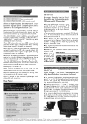
...Camera Recorder IP. •The menu can be controlled by the Camera Control Unit in serial connection. AJ-C10050G Remote Control Cable (50 m / 164 feet) AW-PS551 AC adaptor SHAN-TM700 Tripod Adapter 13 *1: The 1080/29.97PsF, 1080/25PsF and 1080/23.98PsF formats must be selected at Low Cost... to the Camera Control Unit, so detailed camera settings can be made by operating the Remote Operation Panel. •The joystick control lever enables fine manual iris/ pedestal operation. •Scene files and user files can be saved on an SD memory card. •The unit is used. Rear Panel ...
...Camera Recorder IP. •The menu can be controlled by the Camera Control Unit in serial connection. AJ-C10050G Remote Control Cable (50 m / 164 feet) AW-PS551 AC adaptor SHAN-TM700 Tripod Adapter 13 *1: The 1080/29.97PsF, 1080/25PsF and 1080/23.98PsF formats must be selected at Low Cost... to the Camera Control Unit, so detailed camera settings can be made by operating the Remote Operation Panel. •The joystick control lever enables fine manual iris/ pedestal operation. •Scene files and user files can be saved on an SD memory card. •The unit is used. Rear Panel ...
System Camera and Switcher Product Lineup Catalog
Page 36
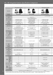
... step) 54 dB (standard) Auto, Off, 6dB, 12dB, 18dB, 24dB Auto*4, Through, 1/4, 1/16, 1/64 Maximum speed during preset: 300°/s Maximum speed during manual: 90°/s Panning Range AW-HE130W/K Serial / IP / IR DC 12 V (AC Adaptor supplied), DC42 V to 57 V (PoE+ power supply) 1.8 A (AC adaptor supplied) 0.6 A (PoE+ power..., 12dB, 18dB, 24dB Up to 100 0.08°/s to 60°/s ±175° Maximum speed during preset: 300°/s Maximum speed during manual: 90°/s Tilting Range -30° to 90°*5 -30° to 210°*5 -30° to 90°*5 Quietness During preset: ...
... step) 54 dB (standard) Auto, Off, 6dB, 12dB, 18dB, 24dB Auto*4, Through, 1/4, 1/16, 1/64 Maximum speed during preset: 300°/s Maximum speed during manual: 90°/s Panning Range AW-HE130W/K Serial / IP / IR DC 12 V (AC Adaptor supplied), DC42 V to 57 V (PoE+ power supply) 1.8 A (AC adaptor supplied) 0.6 A (PoE+ power..., 12dB, 18dB, 24dB Up to 100 0.08°/s to 60°/s ±175° Maximum speed during preset: 300°/s Maximum speed during manual: 90°/s Tilting Range -30° to 90°*5 -30° to 210°*5 -30° to 90°*5 Quietness During preset: ...

