Professional 3D Systems Brochure
Page 4
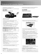
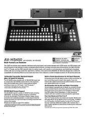
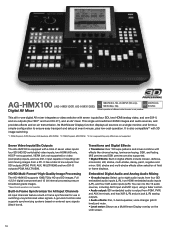
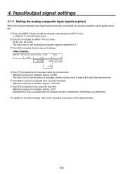
... its memory cards. AV-HS450U1) Specifications Power Supply: AC 100 V-240 V 50Hz/60Hz Power Consumption: 120 W Weight: Approx. 9.8 kg (21.6 lb) (without the optional board AV-HS04M7D. *2: The optional AV-HS04M1 SDI Input Board is required. Left channel/Right channel/Overlay switchable display. *Equipped with HDMI 3D (frame packing) in addition to HD SDI (x2, simultaneous). *Built-in Stereo microphone. *Provided with two XLR connections for either microphone or line input...
... its memory cards. AV-HS450U1) Specifications Power Supply: AC 100 V-240 V 50Hz/60Hz Power Consumption: 120 W Weight: Approx. 9.8 kg (21.6 lb) (without the optional board AV-HS04M7D. *2: The optional AV-HS04M1 SDI Input Board is required. Left channel/Right channel/Overlay switchable display. *Equipped with HDMI 3D (frame packing) in addition to HD SDI (x2, simultaneous). *Built-in Stereo microphone. *Provided with two XLR connections for either microphone or line input...
Professional 3D Systems Brochure
Page 7
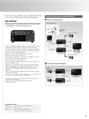
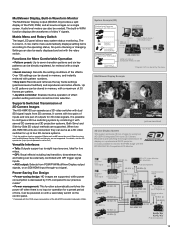
... Card (Rch video data) REFAI 3D Link (D-SUB, USB) Consumer 3DTV 3D Display AG-HPD24 HD SDI (R) AG-HPD24 Specifications Power Source: DC 7.2 V with battery, DC 7.9 V with linear editing system. *3: Without replacing cards. An AVC-Intra Codec, HDMI 3D Output, and USB 3.0 (HOST) Allow Use in a Variety of up to the front panel. •HDMI (3D-compatible) output, HD/SD SDI input/output, video monitor output, audio monitor output, headphone output, REF input, TC input/output, XLR analog audio input...
... Card (Rch video data) REFAI 3D Link (D-SUB, USB) Consumer 3DTV 3D Display AG-HPD24 HD SDI (R) AG-HPD24 Specifications Power Source: DC 7.2 V with battery, DC 7.9 V with linear editing system. *3: Without replacing cards. An AVC-Intra Codec, HDMI 3D Output, and USB 3.0 (HOST) Allow Use in a Variety of up to the front panel. •HDMI (3D-compatible) output, HD/SD SDI input/output, video monitor output, audio monitor output, headphone output, REF input, TC input/output, XLR analog audio input...
Professional 3D Systems Brochure
Page 9
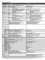
... software, purchased separately)*1 that supports AVCHD video editing. P2 Card (Lch video signal) HD SDI (L)* I REF P2 Card (Rch video signal) 3D Link (D-SUB, USB) "I OR) Color Grading System (Third Party) .rth. The Panasonic professional 3D plasma display can be easily edited by using the BT-3DL2550. BT-3DL2550 Video Monitor 3D video data recorded by the AG-3DA1 can be checked by a computer-based (Windows/Mac), low...
... software, purchased separately)*1 that supports AVCHD video editing. P2 Card (Lch video signal) HD SDI (L)* I REF P2 Card (Rch video signal) 3D Link (D-SUB, USB) "I OR) Color Grading System (Third Party) .rth. The Panasonic professional 3D plasma display can be easily edited by using the BT-3DL2550. BT-3DL2550 Video Monitor 3D video data recorded by the AG-3DA1 can be checked by a computer-based (Windows/Mac), low...
Mixers Switchers Catalogue
Page 4
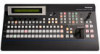
.../24PsF (or 23.98PsF) input signals are supported only by the optional AV-HS04M1/M2/M3/M4/ M5/M6/M7/M7D/M8 boards. And it ideal for 3D camera assist use in -P bus and Aux bus* switching effect) also enables a Mix transition (Aux 1 only). This makes it features a number of display functions for digital cinema production and worldwide operation. Up-Converter, Dot by dot function for P-in -P buses. Borders...
.../24PsF (or 23.98PsF) input signals are supported only by the optional AV-HS04M1/M2/M3/M4/ M5/M6/M7/M7D/M8 boards. And it ideal for 3D camera assist use in -P bus and Aux bus* switching effect) also enables a Mix transition (Aux 1 only). This makes it features a number of display functions for digital cinema production and worldwide operation. Up-Converter, Dot by dot function for P-in -P buses. Borders...
Mixers Switchers Catalogue
Page 8
... 13 inputs,*1 and 10 outputs.*2 *1: When using two AV-HS04M1, M2, M6, or M8 Input Boards. *2: When using two channels, such as standard. Extremely fine objects, such as individual strands of HD/SD formats, including 1080/24PsF, as reduce, slide, squeeze and 3D wipe are also provided to a Cut transition, the Bus transition function (P-in advance, and direct-control buttons enhance operating ease. A gen-lock function also supports...
... 13 inputs,*1 and 10 outputs.*2 *1: When using two AV-HS04M1, M2, M6, or M8 Input Boards. *2: When using two channels, such as standard. Extremely fine objects, such as individual strands of HD/SD formats, including 1080/24PsF, as reduce, slide, squeeze and 3D wipe are also provided to a Cut transition, the Bus transition function (P-in advance, and direct-control buttons enhance operating ease. A gen-lock function also supports...
Mixers Switchers Catalogue
Page 9
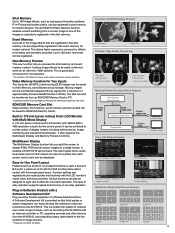
... consecutive effects to eight user buttons for live -relay operation. This is built into the control panel. Plug-in Software Created with WVGA (800 x 480) resolution is particularly convenient for one of display modes, including setting menus, image monitoring and waveform/vectorscope. New Memory Preview This new function lets you split the screen to -Use Panel Layout Features such as a total of 12 crosspoint buttons in each screen, and a clock...
... consecutive effects to eight user buttons for live -relay operation. This is built into the control panel. Plug-in Software Created with WVGA (800 x 480) resolution is particularly convenient for one of display modes, including setting menus, image monitoring and waveform/vectorscope. New Memory Preview This new function lets you split the screen to -Use Panel Layout Features such as a total of 12 crosspoint buttons in each screen, and a clock...
Mixers Switchers Catalogue
Page 13
... Camera Controller. • The switcher's bus footage (Aux, PVW, P-in-P, Key-F) can be selected at the Camera Controller to a monitor screen. (SDI OUT 2 or DVI OUT only) Audio Level Meter This function displays the level of the embedded audio signals (group 1/1ch, 2ch) superimposed on the SDI input signal. This supports the camera's Focus Assist function. • The Pan/Tilt lever and Zoom button on the Camera Controller can be used to change switcher...
... Camera Controller. • The switcher's bus footage (Aux, PVW, P-in-P, Key-F) can be selected at the Camera Controller to a monitor screen. (SDI OUT 2 or DVI OUT only) Audio Level Meter This function displays the level of the embedded audio signals (group 1/1ch, 2ch) superimposed on the SDI input signal. This supports the camera's Focus Assist function. • The Pan/Tilt lever and Zoom button on the Camera Controller can be used to change switcher...
Mixers Switchers Catalogue
Page 14
... transport and setup at event venues, plus low-cost operation. You can mix the 10 audio sources, including AUX input and MIC input, using a fader control. • Audio output: SDI embedded audio is not possible. Its MultiViewer Display function displays all -in switching unsynchronized video signals. Built-in Frame Synchronizer for All Input Channels All input channels feature a built-in frame synchronizer for use in -one digital AV mixer integrates a video switcher with effects like chroma keying, luminance keying, DSK, and...
... transport and setup at event venues, plus low-cost operation. You can mix the 10 audio sources, including AUX input and MIC input, using a fader control. • Audio output: SDI embedded audio is not possible. Its MultiViewer Display function displays all -in switching unsynchronized video signals. Built-in Frame Synchronizer for All Input Channels All input channels feature a built-in frame synchronizer for use in -one digital AV mixer integrates a video switcher with effects like chroma keying, luminance keying, DSK, and...
Mixers Switchers Catalogue
Page 15
...://pro-av.panasonic.net/en/3d/) Versatile Interfaces • Tally: Outputs support up to eight input sources. It is no input or operation for retrieval with the BT-3DL2550 3D-Compatible LCD Monitor. Settings can be directly registered, for a preset period of time. Over 100 settings can operate as MultiViewer Display, WFM, and title mix, are connected, they can serve as ME cannot be used. Up to monitor the...
...://pro-av.panasonic.net/en/3d/) Versatile Interfaces • Tally: Outputs support up to eight input sources. It is no input or operation for retrieval with the BT-3DL2550 3D-Compatible LCD Monitor. Settings can be directly registered, for a preset period of time. Over 100 settings can operate as MultiViewer Display, WFM, and title mix, are connected, they can serve as ME cannot be used. Up to monitor the...
Mixers Switchers Catalogue
Page 18
... boards AV-HS04 M1, M2, M3, M4, M5, M6 and M7. *3: For information on input/output signals, see page 10, "Input Formats." *4: AUX BUS 1 is incorporated - Audio Input/Output - - memories can be retained even when the power is turned off by the control panel, Capacity: Maximum 32 GB (SDHC Memory Card compatible) Still image file: Loading/saving, setup data: backup CD-ROM (Operating instructions / Image transmission software), AC adapter (for control panel),Power cable (for mainframe and AC adapter), CAT5E cable...
... boards AV-HS04 M1, M2, M3, M4, M5, M6 and M7. *3: For information on input/output signals, see page 10, "Input Formats." *4: AUX BUS 1 is incorporated - Audio Input/Output - - memories can be retained even when the power is turned off by the control panel, Capacity: Maximum 32 GB (SDHC Memory Card compatible) Still image file: Loading/saving, setup data: backup CD-ROM (Operating instructions / Image transmission software), AC adapter (for control panel),Power cable (for mainframe and AC adapter), CAT5E cable...
Mixers Switchers Catalogue
Page 19
..., Mono, Time effects, Decay, Paint, Nega, Mirror 1 1 Linear key, Luminance key, Chroma key*8 Linear key, Luminance key, Chroma key, Full key Mix Cut, Mix, Wipe (including DVE) - Wipe x 6 - 1 - PinP Preset, Effect dissolve function Event memory (100 patterns), Key learning (20 patterns) *7: May store and recall up to 10 presets (per camera) with HDCP) AUX input: Pin jack: 1 line (L and R),-10 dBV, High impedance, unbalanced MIC input: M6 x 1 line, -60 dBV, 2 kΩ, monaural, unbalanced AUDIO output: PGM...
..., Mono, Time effects, Decay, Paint, Nega, Mirror 1 1 Linear key, Luminance key, Chroma key*8 Linear key, Luminance key, Chroma key, Full key Mix Cut, Mix, Wipe (including DVE) - Wipe x 6 - 1 - PinP Preset, Effect dissolve function Event memory (100 patterns), Key learning (20 patterns) *7: May store and recall up to 10 presets (per camera) with HDCP) AUX input: Pin jack: 1 line (L and R),-10 dBV, High impedance, unbalanced MIC input: M6 x 1 line, -60 dBV, 2 kΩ, monaural, unbalanced AUDIO output: PGM...

Operating Instructions
Page 5
... black 78 3-8. Switching the AUX output 80 3-9-1. Frame memories 89 3-11-1. Setting the frame synchronizer 97 4-1-2. Setting the input mode 98 4-1-3. Setting the DVI input signals (option 107 4-2-1. Setting the split frame and characters ....125 4-8-3. Setting the on-screen display (OSD 129 4-10. DSK transitions 74 3-6-4. DSK adjustments 75 3-6-6. Memory registration and recall items......84 3-10-2. Deleting the operations stored in Flash Memory 90 3-12. Effect dissolve 88 3-11. Assigning the output signals 113 4-4. Selecting...
... black 78 3-8. Switching the AUX output 80 3-9-1. Frame memories 89 3-11-1. Setting the frame synchronizer 97 4-1-2. Setting the input mode 98 4-1-3. Setting the DVI input signals (option 107 4-2-1. Setting the split frame and characters ....125 4-8-3. Setting the on-screen display (OSD 129 4-10. DSK transitions 74 3-6-4. DSK adjustments 75 3-6-6. Memory registration and recall items......84 3-10-2. Deleting the operations stored in Flash Memory 90 3-12. Effect dissolve 88 3-11. Assigning the output signals 113 4-4. Selecting...
Operating Instructions
Page 6
... control 144 5-8. External interfaces 154 6-1. Connecting the control panel and mainframe 154 6-2. Button assignments 135 5-3-1. Alarm status displays 151 5-8-2. Mainframe 154 6-2-1. Image transmission functions......... 158 8. Setting the date and time 137 5-5. Editor control 141 5-7-3. TALLY/GPI 157 7. Setting the crosspoints 132 5-2-1. Setting the crosspoint switching 134 5-3. Alarm message 151 5-8-3. Initializing Fader 153 6. LAN 154 6-2-2. Initialization 153 5-9-1. Contents 5. Setting the user buttons 135 5-4. Initializing Setting Data...
... control 144 5-8. External interfaces 154 6-1. Connecting the control panel and mainframe 154 6-2. Button assignments 135 5-3-1. Alarm status displays 151 5-8-2. Mainframe 154 6-2-1. Image transmission functions......... 158 8. Setting the date and time 137 5-5. Editor control 141 5-7-3. TALLY/GPI 157 7. Setting the crosspoints 132 5-2-1. Setting the crosspoint switching 134 5-3. Alarm message 151 5-8-3. Initializing Fader 153 6. LAN 154 6-2-2. Initialization 153 5-9-1. Contents 5. Setting the user buttons 135 5-4. Initializing Setting Data...

Operating Instructions
Page 7
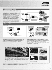
... input/output applications are provided under the standard specifications. similarly, when two option boards for all the inputs so that systems can be expanded to the synchronization of a mainframe and control panel. By using external sync signals (BB or TRI signals) as a reference are installed, the maximum number of input signal lines can be input. Despite its compact dimensions of forms. Incorporated in the switcher's inputs are installed, the maximum number of input/output formats...
... input/output applications are provided under the standard specifications. similarly, when two option boards for all the inputs so that systems can be expanded to the synchronization of a mainframe and control panel. By using external sync signals (BB or TRI signals) as a reference are installed, the maximum number of input signal lines can be input. Despite its compact dimensions of forms. Incorporated in the switcher's inputs are installed, the maximum number of input/output formats...

Operating Instructions
Page 16
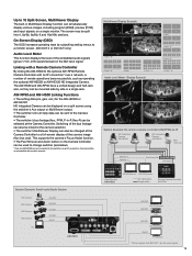
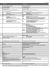
... using the supplied CAT5E cable. 5: Do not connect to a public line when connecting a PC. When internal synchronization is selected, the reference 4: Connect the PANEL connector directly to 4 (3) OUTPUT 5, 6 OUTPUT (DVI-D) 5, 6 OUTPUT A1, A2 INPUT B1, B2 Option slot B OUTPUT B1, B2 AC IN AC/DC AC/DC Power REF REF IN/OUT (1) REF OUT (2) RJ45 LAN (5) RJ45 PANEL (4) SD PC memory card...
... using the supplied CAT5E cable. 5: Do not connect to a public line when connecting a PC. When internal synchronization is selected, the reference 4: Connect the PANEL connector directly to 4 (3) OUTPUT 5, 6 OUTPUT (DVI-D) 5, 6 OUTPUT A1, A2 INPUT B1, B2 Option slot B OUTPUT B1, B2 AC IN AC/DC AC/DC Power REF REF IN/OUT (1) REF OUT (2) RJ45 LAN (5) RJ45 PANEL (4) SD PC memory card...
Operating Instructions
Page 96
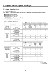
... be set . 96 AV-HS04M3 DVI-I input 2 lines AV-HS04M6 Analog composite input 2 lines AV-HS04M8 DVI-D input 2 line Setting menu and numbers of the following option boards has been connected. AV-HS04M1 (SDI Input Board) AV-HS04M2 (Analog Input Board) AV-HS04M3 (DVI Input Board) AV-HS04M6 (Analog Composite Input Board) AV-HS04M8 (Full-HD DVI Input Board) Input connector IN1 to IN8 IN9 to IN16 IN13 to IN6 are SDI signal inputs. Input signal settings...
... be set . 96 AV-HS04M3 DVI-I input 2 lines AV-HS04M6 Analog composite input 2 lines AV-HS04M8 DVI-D input 2 line Setting menu and numbers of the following option boards has been connected. AV-HS04M1 (SDI Input Board) AV-HS04M2 (Analog Input Board) AV-HS04M3 (DVI Input Board) AV-HS04M6 (Analog Composite Input Board) AV-HS04M8 (Full-HD DVI Input Board) Input connector IN1 to IN8 IN9 to IN16 IN13 to IN6 are SDI signal inputs. Input signal settings...
Operating Instructions
Page 106
...°) Adjustment of the optional board. 106 For details on the other settings, refer to the operating instructions of Hue is possible when the system format is selected for X. Turn [F2] to "2-1-5. Input/output signal settings 4-1-7. LCD menu area". Turn [F1] to display the INPUT XX sub menu. (X: A1, A2, B1 or B2) The input used to set . Press the [INPUT] button to light its...
...°) Adjustment of the optional board. 106 For details on the other settings, refer to the operating instructions of Hue is possible when the system format is selected for X. Turn [F2] to "2-1-5. Input/output signal settings 4-1-7. LCD menu area". Turn [F1] to display the INPUT XX sub menu. (X: A1, A2, B1 or B2) The input used to set . Press the [INPUT] button to light its...

Operating Instructions
Page 186
Specifications Control panel [AV-HS450C1N] Control I/O External media Ambient operating temperature Humidity Power supply Dimensions (W H D) Weight MAINFRAME 100 Mbps 1 For connecting the mainframe TALLY/GPI INPUT: 8 inputs OUTPUT: 8 outputs ALARM: 1 output SD memory cards Memory size supported: Max. 32 GB (SDHC memory cards supported) Still image files: Load, save Setup data: Backup 32 °F to 104 °F (0 °C to 40 °C) 10 % to 90 % (no condensation) DC 12 V, 0.8 A Redundant operation enabled...
Specifications Control panel [AV-HS450C1N] Control I/O External media Ambient operating temperature Humidity Power supply Dimensions (W H D) Weight MAINFRAME 100 Mbps 1 For connecting the mainframe TALLY/GPI INPUT: 8 inputs OUTPUT: 8 outputs ALARM: 1 output SD memory cards Memory size supported: Max. 32 GB (SDHC memory cards supported) Still image files: Load, save Setup data: Backup 32 °F to 104 °F (0 °C to 40 °C) 10 % to 90 % (no condensation) DC 12 V, 0.8 A Redundant operation enabled...

Operating Instructions
Page 187
... the reference signal for the SD format. This refers to the effect where the display is used as the V ancillary data (VANC). The key is referred to the next image. Word AB Bus system Ancillary Data Aspect ratio AUX [Auxiliary Bus] AVDL [Automatic Video Delayline] BB [Black burst] Border Chroma key Clip Color Background Cut Density Dot by signals other than the main line output signals. The data superimposed...
... the reference signal for the SD format. This refers to the effect where the display is used as the V ancillary data (VANC). The key is referred to the next image. Word AB Bus system Ancillary Data Aspect ratio AUX [Auxiliary Bus] AVDL [Automatic Video Delayline] BB [Black burst] Border Chroma key Clip Color Background Cut Density Dot by signals other than the main line output signals. The data superimposed...

Operating Instructions
Page 189
... and recalled. A function that indicates the program output status on the control panel is output from one image is gradually replaced by which one image to an external device. The bus which always carries the program output signals. Wipe, mix and other setting information can be saved in which video signals in various SD and HD formats are available for the images during switching. A video effect in this memory. This...
... and recalled. A function that indicates the program output status on the control panel is output from one image is gradually replaced by which one image to an external device. The bus which always carries the program output signals. Wipe, mix and other setting information can be saved in which video signals in various SD and HD formats are available for the images during switching. A video effect in this memory. This...


