Operating Instructions
Page 1
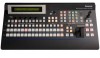
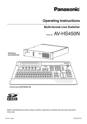
Printed in Japan 3TR006327AAC AV-HS450N Mainframe [AV-HS450U1N] OFFPOWER1 ON POWER1 ALARM1 OFFPOWER2 ON POWER2 ALARM2 Multi-format Live Switcher AV-HS450 POWER ALARM Multi-format Live Switcher AV-HS450 Control panel [AV-HS450C1N] Before operating this product, please read the instructions carefully and save this manual for future use. Operating Instructions Multi-format Live Switcher Model No.
Printed in Japan 3TR006327AAC AV-HS450N Mainframe [AV-HS450U1N] OFFPOWER1 ON POWER1 ALARM1 OFFPOWER2 ON POWER2 ALARM2 Multi-format Live Switcher AV-HS450 POWER ALARM Multi-format Live Switcher AV-HS450 Control panel [AV-HS450C1N] Before operating this product, please read the instructions carefully and save this manual for future use. Operating Instructions Multi-format Live Switcher Model No.

Operating Instructions
Page 2
... shock or fire hazard due to overheating, ensure that an apparatus with arrowhead symbol, within an equilateral triangle is operated in accordance with the instruction manual, may be required to external units. For CANADA This class A digital apparatus complies with the limits for a class A digital device, pursuant to maintain adequate ventilation...
... shock or fire hazard due to overheating, ensure that an apparatus with arrowhead symbol, within an equilateral triangle is operated in accordance with the instruction manual, may be required to external units. For CANADA This class A digital apparatus complies with the limits for a class A digital device, pursuant to maintain adequate ventilation...

Operating Instructions
Page 4
How to install the option boards 14 1-4. Block diagram 16 1-4-2. Transition area 22 2-1-5. Rear panel connections area 31 3. Selecting the bus mode 36 3-1-4. Manual transition (using the SHIFT function 33 3-1-3. Setting the IMAGE effects 38 3-2-2. Selecting the background for use 10 Trademarks and Registered Trademarks 11 Disclaimer of Warranty ...
How to install the option boards 14 1-4. Block diagram 16 1-4-2. Transition area 22 2-1-5. Rear panel connections area 31 3. Selecting the bus mode 36 3-1-4. Manual transition (using the SHIFT function 33 3-1-3. Setting the IMAGE effects 38 3-2-2. Selecting the background for use 10 Trademarks and Registered Trademarks 11 Disclaimer of Warranty ...

Operating Instructions
Page 24
When it is completed. The LED corresponding to manual operation as soon as it has been operated during auto transition, auto transition will go, the transition is moved as far as the fader position ...
When it is completed. The LED corresponding to manual operation as soon as it has been operated during auto transition, auto transition will go, the transition is moved as far as the fader position ...

Operating Instructions
Page 37
... the fader lever to 999f can be switched to light its indicator lights in amber. 3-1-5. Manual transition (using the TIME menu. Press the [TIME] button to manual operation as soon as the fader position overtakes the amount of the selected button lights in amber...BKGD] button and [KEY] button are pressed at an interim setting, the transition is executed in the time remaining from 0 to execute transitions manually. If the fader lever has been operated during the transition Bottom LED only lights: PST/B output 3-1-6. LCD menu area". Turn [...
... the fader lever to 999f can be switched to light its indicator lights in amber. 3-1-5. Manual transition (using the TIME menu. Press the [TIME] button to manual operation as soon as the fader position overtakes the amount of the selected button lights in amber...BKGD] button and [KEY] button are pressed at an interim setting, the transition is executed in the time remaining from 0 to execute transitions manually. If the fader lever has been operated during the transition Bottom LED only lights: PST/B output 3-1-6. LCD menu area". Turn [...

Operating Instructions
Page 51
...;On the KEY menu, turn [F1] to display the KEY sub menu. Turn [F5] to the preview output. Alternatively, execute the transition manually by operating the fader lever. During key in red when the transition is output to the preview output. Auto: The preview image of the [KEY...
...;On the KEY menu, turn [F1] to display the KEY sub menu. Turn [F5] to the preview output. Alternatively, execute the transition manually by operating the fader lever. During key in red when the transition is output to the preview output. Auto: The preview image of the [KEY...

Operating Instructions
Page 53
... menu. Press [F2] to select "Cmpsit" using the Mode item. To undo what has been sampled, press [F5]. To execute the sampling manually Press the [KEY/CKEY] button to light its indicator, and display the CHR KEY menu. Proc.FG Cln.FG Turn [F2...
... menu. Press [F2] to select "Cmpsit" using the Mode item. To undo what has been sampled, press [F5]. To execute the sampling manually Press the [KEY/CKEY] button to light its indicator, and display the CHR KEY menu. Proc.FG Cln.FG Turn [F2...

Operating Instructions
Page 62
Manual: The area that is set using the MaskAdj sub menu is masked. 4:3: The signals are taken to mask the key signals using the mask signal ... to 50.00 −50.00 to 50.00 −50.00 to display the MaskAdj sub menu. KEY 10|Mask |Invert | | Mask | Off| Off| | Manual On 4:3 Turn [F2], and select the masking method using the Invert item. Off: The mask signal is not inverted. Turn [F1...
Manual: The area that is set using the MaskAdj sub menu is masked. 4:3: The signals are taken to mask the key signals using the mask signal ... to 50.00 −50.00 to 50.00 −50.00 to display the MaskAdj sub menu. KEY 10|Mask |Invert | | Mask | Off| Off| | Manual On 4:3 Turn [F2], and select the masking method using the Invert item. Off: The mask signal is not inverted. Turn [F1...

Operating Instructions
Page 70
... the default values) TOP (40) 50 0 BOTTOM (-40) -50 -50 0 50 (-40) LEFT (40) RIGHT Area trimmed Area where PinP is 4:3 Manual: Trimming using the value set the trimming values. Operation F2 Parameter Left Description of setting Trimming value at left -right symmetry.) Turn [F1...00 F5 Right Trimming value at right −50.00 to select the trimming type using the Manual item. LCD menu area". Turn [F1] to be performed during the manual setting using the Trim item. However, the Left setting cannot exceed the Right setting (and vice ...
... the default values) TOP (40) 50 0 BOTTOM (-40) -50 -50 0 50 (-40) LEFT (40) RIGHT Area trimmed Area where PinP is 4:3 Manual: Trimming using the value set the trimming values. Operation F2 Parameter Left Description of setting Trimming value at left -right symmetry.) Turn [F1...00 F5 Right Trimming value at right −50.00 to select the trimming type using the Manual item. LCD menu area". Turn [F1] to be performed during the manual setting using the Trim item. However, the Left setting cannot exceed the Right setting (and vice ...

Operating Instructions
Page 77
... [F1] to display the Mask sub menu. Basic operations 3-6-7. LCD menu area". Turn [F1] to display the MaskAdj sub menu. Manual: The area that is set using the MaskAdj sub menu is masked. 4:3: The signals are masked to the 4:3 aspect ratio. Turn ...menu). Refer to be masked. On: The mask signal is effective Video signal range 77 DSK1 6|Mask |Invert | | Mask | Off| Off| | Manual On 4:3 Turn [F2], and select the masking method using the Invert item. DSK1 7|Left |Top |Bottom |Right MaskAdj | −25.00|...
... [F1] to display the Mask sub menu. Basic operations 3-6-7. LCD menu area". Turn [F1] to display the MaskAdj sub menu. Manual: The area that is set using the MaskAdj sub menu is masked. 4:3: The signals are masked to the 4:3 aspect ratio. Turn ...menu). Refer to be masked. On: The mask signal is effective Video signal range 77 DSK1 6|Mask |Invert | | Mask | Off| Off| | Manual On 4:3 Turn [F2], and select the masking method using the Invert item. DSK1 7|Left |Top |Bottom |Right MaskAdj | −25.00|...

Operating Instructions
Page 90
...] to "2-1-5. 3. Whether to automatically save the image data stored in the flash memory area. The [F5] switch becomes enabled when "Manual" is turned off before the saving operation is transferred from FMEM1 to FMEM4. Press the [F5] switch (Exec) to display the Memory... and display the FMEM menu. Refer to select the saving method in the Select item. AUTO: Automatic saving Manual: Manual saving Turn [F3] to manually save data in the frame memory when the data is completed. Light the [FMEM] button by saving them...
...] to "2-1-5. 3. Whether to automatically save the image data stored in the flash memory area. The [F5] switch becomes enabled when "Manual" is turned off before the saving operation is transferred from FMEM1 to FMEM4. Press the [F5] switch (Exec) to display the Memory... and display the FMEM menu. Refer to select the saving method in the Select item. AUTO: Automatic saving Manual: Manual saving Turn [F3] to manually save data in the frame memory when the data is completed. Light the [FMEM] button by saving them...
Operating Instructions
Page 96
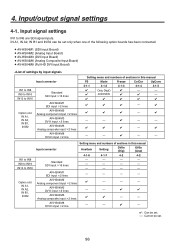
...; - - - - - - - - - - - AV-HS04M3 DVI-I input 2 lines AV-HS04M6 Analog composite input 2 lines AV-HS04M8 DVI-D input 2 line Setting menu and numbers of sections in this manual Input connector AnaGain Setting DVIIn (Dig) DVIIn (Ana) 4-1-6 4-1-7 4-2 4-2 Standard SDI input 16...
...; - - - - - - - - - - - AV-HS04M3 DVI-I input 2 lines AV-HS04M6 Analog composite input 2 lines AV-HS04M8 DVI-D input 2 line Setting menu and numbers of sections in this manual Input connector AnaGain Setting DVIIn (Dig) DVIIn (Ana) 4-1-6 4-1-7 4-2 4-2 Standard SDI input 16...

Operating Instructions
Page 102
...the third menu of CC Trn2. R: red, G: green, B: blue Turn [F4] to be compensated. INPUT XX|CC Trn1|RGB | 9/13 | |Manual |GrayPos R| ALL| 0.50 G Free 0.25 B | 0.75 BlackLv Output level GrayPos GrayLv Input level Turn [F3] to select the color to set ...the gray level position using the Manual item. WhiteLv 102 4. Free: Each of the R, G and B colors is set separately. Turn [F5] to set the compensation mode ...
...the third menu of CC Trn2. R: red, G: green, B: blue Turn [F4] to be compensated. INPUT XX|CC Trn1|RGB | 9/13 | |Manual |GrayPos R| ALL| 0.50 G Free 0.25 B | 0.75 BlackLv Output level GrayPos GrayLv Input level Turn [F3] to select the color to set ...the gray level position using the Manual item. WhiteLv 102 4. Free: Each of the R, G and B colors is set separately. Turn [F5] to set the compensation mode ...

Operating Instructions
Page 112
...OUT B2 Standard SDI output 4 lines Standard DVI-D output 2 lines AV-HS04M4 Analog component output 2 lines AV-HS04M5 DVI-I output 1 line Analog component output 1 line AV-HS04M7 SDI output 2 lines Setting menu and numbers of the following option ... (Analog Output Board) AV-HS04M5 (DVI/Analog Output Board) AV-HS04M7 (SDI Output Board) Output connector OUT1 to OUT4 are DVI-D signal outputs. OUT A1, OUT A2, OUT B1 and OUT B2 can be set only when one of sections in this manual Asign DVIOut (Dig) DVIOut (Ana) DownCnv ...
...OUT B2 Standard SDI output 4 lines Standard DVI-D output 2 lines AV-HS04M4 Analog component output 2 lines AV-HS04M5 DVI-I output 1 line Analog component output 1 line AV-HS04M7 SDI output 2 lines Setting menu and numbers of the following option ... (Analog Output Board) AV-HS04M5 (DVI/Analog Output Board) AV-HS04M7 (SDI Output Board) Output connector OUT1 to OUT4 are DVI-D signal outputs. OUT A1, OUT A2, OUT B1 and OUT B2 can be set only when one of sections in this manual Asign DVIOut (Dig) DVIOut (Ana) DownCnv ...

Operating Instructions
Page 149
... [F5] switch. 5. Middle: Control is exercised at the slowest speed. When controlling the pan-tilt head's power to On, turn [F5] to set to manual operation. If the crosspoint buttons (PGM/A 1 to 32 and PST/B 1 to 32) are held down when "P/ TCont" or "P/TDirt" is initiated. CAM 2|CTL CamCTL2...
... [F5] switch. 5. Middle: Control is exercised at the slowest speed. When controlling the pan-tilt head's power to On, turn [F5] to set to manual operation. If the crosspoint buttons (PGM/A 1 to 32 and PST/B 1 to 32) are held down when "P/ TCont" or "P/TDirt" is initiated. CAM 2|CTL CamCTL2...

Operating Instructions
Page 163
... Size −100.00 to 100.00 −100.00 to 100.00 0.0 to 400.0 0.00 0.00 100.0 Light On, Off Off Mask Invert Off, Manual, 4:3 On, Off Off Off Left Top Bottom Right −50.00 to 50.00 −50.00 to 50.00 −50.00 to 50...
... Size −100.00 to 100.00 −100.00 to 100.00 0.0 to 400.0 0.00 0.00 100.0 Light On, Off Off Mask Invert Off, Manual, 4:3 On, Off Off Off Left Top Bottom Right −50.00 to 50.00 −50.00 to 50.00 −50.00 to 50...

Operating Instructions
Page 165
... Setting range Default value Parameter 1 Parameter 2 Parameter 3 Parameter 4 Turn F2 to select. Turn F4 to select. Turn F5 to select. Turn F3 to select. Trim Manual Manual, Off, 4:3 Free, Pair (The setting is fixed at Off when Circle has been set for the Shape item on the PinP1 sub menu.) Off....00 −50.00 to 50.00 0.00 to 100.00 0.00 0.00 25.00 X Y Z -360 to 360 -360 to 360 -360 to 360 0 0 0 Trim Manual Manual, Off, 4:3 Free, Pair Off Free Left Top Bottom Right −50.00 to 50.00 −50.00 to 50.00 −50.00 to...
... Setting range Default value Parameter 1 Parameter 2 Parameter 3 Parameter 4 Turn F2 to select. Turn F4 to select. Turn F5 to select. Turn F3 to select. Trim Manual Manual, Off, 4:3 Free, Pair (The setting is fixed at Off when Circle has been set for the Shape item on the PinP1 sub menu.) Off....00 −50.00 to 50.00 0.00 to 100.00 0.00 0.00 25.00 X Y Z -360 to 360 -360 to 360 -360 to 360 0 0 0 Trim Manual Manual, Off, 4:3 Free, Pair Off Free Left Top Bottom Right −50.00 to 50.00 −50.00 to 50.00 −50.00 to...

Operating Instructions
Page 166
..., 315 Off 2 0 Hue Sat Lum Load ↓ 0.0 to 359.9 0.0 0.0 to 100.0 0.0 0.0 to 108.0 0.0 White, Yellow, Cyan, Green, Magenta, Red, Blue, Black Black Mask Invert Off, Manual, 4:3 On, Off Off Off Left Top Bottom Right −50.00 to 50.00 −50.00 to 50.00 −50.00 to 50...
..., 315 Off 2 0 Hue Sat Lum Load ↓ 0.0 to 359.9 0.0 0.0 to 100.0 0.0 0.0 to 108.0 0.0 White, Yellow, Cyan, Green, Magenta, Red, Blue, Black Black Mask Invert Off, Manual, 4:3 On, Off Off Off Left Top Bottom Right −50.00 to 50.00 −50.00 to 50.00 −50.00 to 50...

Operating Instructions
Page 167
..., 315 Off 2 0 Hue Sat Lum Load ↓ 0.0 to 359.9 0.0 to 100.0 0.0 to 108.0 White, Yellow, Cyan, Green, Magenta, Red, Blue, Black 0.0 0.0 0.0 Black Mask Invert Off, Manual, 4:3 On, Off Off Off Left Top Bottom Right −50.00 to 50.00 −50.00 to 50.00 −50.00 to 50...
..., 315 Off 2 0 Hue Sat Lum Load ↓ 0.0 to 359.9 0.0 to 100.0 0.0 to 108.0 White, Yellow, Cyan, Green, Magenta, Red, Blue, Black 0.0 0.0 0.0 Black Mask Invert Off, Manual, 4:3 On, Off Off Off Left Top Bottom Right −50.00 to 50.00 −50.00 to 50.00 −50.00 to 50...

Operating Instructions
Page 172
... 1.00 0.00 B-R -1.00 to 1.00 0.00 Limiter CLEAR ↓ Off, 108, 104, 100 Prc, Trn, MTX, ALL 100 ALL Slice -7.0 to 108.0 0.0 Hue 0.0 to 359.9 0.0 Manual GrayPos Free, ALL 0.25 to 0.75 ALL 0.50 GrayLv WhiteLv 0.25 to 0.75 0.50 to 1.00 0.50 1.00 R-B -1.00 to 1.00 0.00 G-B -1.00 to 1.00...
... 1.00 0.00 B-R -1.00 to 1.00 0.00 Limiter CLEAR ↓ Off, 108, 104, 100 Prc, Trn, MTX, ALL 100 ALL Slice -7.0 to 108.0 0.0 Hue 0.0 to 359.9 0.0 Manual GrayPos Free, ALL 0.25 to 0.75 ALL 0.50 GrayLv WhiteLv 0.25 to 0.75 0.50 to 1.00 0.50 1.00 R-B -1.00 to 1.00 0.00 G-B -1.00 to 1.00...

